How to Prevent Wrinkles in Tube Bending: Causes, Tooling and Setup — Rewrite Draft
News 2026-10-22
A wrinkle normally begins on the inside of a tube bend, where the material is being compressed. If the tube wall cannot support that compression, it buckles instead of flowing smoothly around the bend die. The visible wave is the result—but not always the root cause.
In production, operators sometimes respond by increasing pressure everywhere. That can stop one symptom while creating another: deeper clamp marks, excessive wall thinning or a damaged surface. A better method is to identify when the wrinkle starts, then check the tube, tooling and settings in a fixed order.
This troubleshooting guide is intended for rotary draw bending of stainless steel, carbon steel, aluminum and copper tubes. It explains what to inspect before changing the machine program and what information Jiuqiang needs when evaluating a difficult part.
First identify the defect correctly
Not every distorted bend is a wrinkle. Look at the location and shape before adjusting the process.
| Visible symptom | What may be happening | First item to check |
|---|---|---|
| Regular waves on the inside radius | The compressed wall is buckling | Wiper die, mandrel support and pressure-die setting |
| Tube becomes flat through the bend | The cross-section is collapsing | Mandrel type, position and tool fit |
| Outside wall becomes very thin or cracks | The material is being stretched beyond a stable limit | Radius, material condition and lubrication |
| Deep mark near the clamp area | The clamp is slipping or gripping too aggressively | Clamp-die groove, pressure and cleanliness |
| Angle changes from part to part | Springback or tube slip is inconsistent | Material batch, clamping and compensation |
| Wrinkle appears only near the end of a bend | Support or pressure changes during the stroke | Mandrel location, pressure-die travel and boost timing |
A photo should show the complete bend, not only a close-up of the defect. Mark the tangent line and direction of bending. If possible, measure the outside diameter and wall thickness instead of relying only on the purchase label.
Three dimensions govern the difficulty
The starting point is the tube outside diameter (D), wall thickness (t) and centerline radius (CLR). A large D-to-t relationship means the tube is relatively thin. A small CLR-to-D relationship means the bend is relatively tight. When a thin wall and tight radius occur together, the process has less margin and usually needs stronger internal and external support.
These ratios are useful for comparison, but they do not replace a bending test. Stainless steel grades, aluminum tempers, welded seams and dimensional tolerances can change the result. A rule developed for one material should not be copied blindly to another.
Also check the straight length available for clamping. A perfectly designed mandrel cannot solve a part that gives the clamp die too little material to hold. Holes, slots, brackets or previous bends close to the tangent can also weaken support or interfere with the tooling.
What each tool does
Bend die
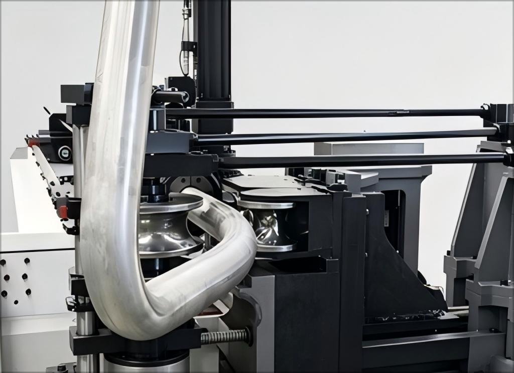
The bend die establishes the radius and carries the tube around the curve. Its groove must match the tube. An oversized or damaged groove gives the tube room to move and deform; an undersized groove can mark the surface.
Clamp die
The clamp die must transmit the bending force without allowing the tube to slip. Increasing clamp pressure is not the first solution when the groove is worn, dirty or too short. Slippage changes the angle and can pull material into an unstable position.
Pressure die
The pressure die supports the straight tube as it enters the bend. Its position, force and movement affect how material flows. Too little support can allow buckling. Excessive drag can increase thinning and surface marks.
Mandrel
The mandrel supports the tube from the inside. Plug mandrels suit less demanding work, while ball mandrels provide support deeper into a difficult bend. A mandrel that is too far behind the tangent does not support the critical area. Moving it too far forward can increase drag, damage the tube or overload the tooling.
Wiper die
The wiper die controls the compressed wall immediately behind the bend tangent. It is especially important for thin-wall tubes and tight radii. Its tip must be sharp enough, correctly positioned and properly supported. A worn tip often produces a wrinkle that returns no matter how many program changes are made.
A practical setup sequence
When a part wrinkles, return to a known setup and work through the following sequence. Record every change; otherwise, a good setting may be found and then lost.
- Verify the tube. Measure diameter and wall thickness at several locations. Confirm material grade, weld seam and batch. Check for dents or ovality before bending.
- Clean and inspect the tools. Remove chips and hardened lubricant. Look for worn grooves, damaged edges and contamination that can scratch stainless steel or aluminum.
- Confirm tool alignment. The bend die, clamp die and pressure die should support the same tube centerline. Misalignment can twist the part and create uneven loading.
- Set the mandrel position. Begin with the tooling supplier’s reference position and adjust in small, measured steps. Record the distance from the tangent.
- Set the wiper die. Confirm tip condition, rake and contact near the tangent. Replace a worn insert rather than compensating indefinitely with pressure.
- Check clamping. Use enough force to stop slip. If more force leaves heavy marks, inspect the groove and available clamp length.
- Set pressure-die support. Adjust support and movement so the tube feeds smoothly without uncontrolled compression or excessive drag.
- Apply suitable lubrication. Lubricate the contact and internal support areas according to the material and downstream process.
- Run one controlled trial. Mark the tube, observe where the defect begins and measure the result before changing another variable.
Do not use speed as the first adjustment
Slowing the bending speed sometimes improves control, but speed alone rarely fixes incorrect tooling. If the mandrel is out of position or the wiper tip is worn, a slower cycle may simply produce the same wrinkle more slowly.
Use speed after confirming the mechanical setup. Some materials respond better to a steady, controlled stroke than to an abrupt start or stop. Multi-speed programming can be useful around difficult sections, but the change should be supported by trial results.
Material-specific points
Stainless steel
Stainless steel generally produces noticeable springback and can work-harden. Consistent grade and wall thickness matter. Polished surfaces require clean tools and careful handling because a good shape can still be rejected for scratches. Do not allow carbon-steel chips to remain on stainless tooling contact areas.
Aluminum
Aluminum surface damage and galling are common concerns. Alloy and temper strongly affect bendability. A part that bends in one temper may crack or deform after a material change. Tool finish and lubricant compatibility deserve special attention.
Carbon steel and welded tube
Carbon steel is often easier to form, but a thin wall can still wrinkle. With welded tube, keep the seam orientation consistent during trials. If the seam moves randomly between parts, it becomes difficult to determine whether a setting change or the tube itself caused the variation.
When the bend radius should be changed
There is a limit to what process adjustment can achieve. If a part combines a very thin wall, tight radius, short clamp length and strict ovality requirement, the design may need a larger radius, a different material condition or a revised bend sequence.
Discuss this before tooling is finalized. A small design change can produce a larger improvement than repeated setup correction. If the radius is fixed for assembly reasons, the supplier may need a more advanced mandrel, wiper arrangement, pressure-die assist or boost function.
Create a bend record that can be repeated
Once a good part is achieved, record more than the CNC program. Include tube supplier and batch, measured wall thickness, tool identification, mandrel position, wiper-die setting, clamp and pressure values, lubricant, speed and springback compensation.
Keep an approved first article near the machine and check production at planned intervals. If wrinkles return, compare the process with the record before making a new program. This is particularly valuable after a tool change, maintenance work or material delivery.
How Jiuqiang evaluates a wrinkle problem
Useful troubleshooting begins with evidence. Send the material grade, outside diameter, wall thickness, centerline radius, bend angle and complete part drawing. Add clear photos of the defect, tool arrangement and unbent tube. If possible, identify the machine model, mandrel type, wiper die and current setup values.
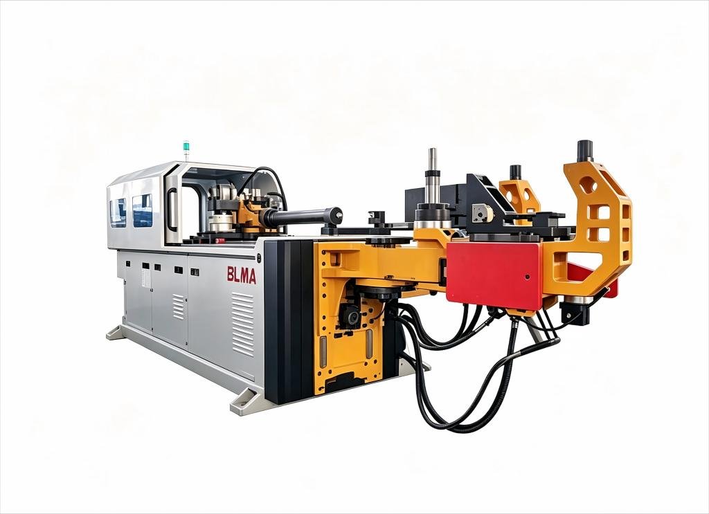
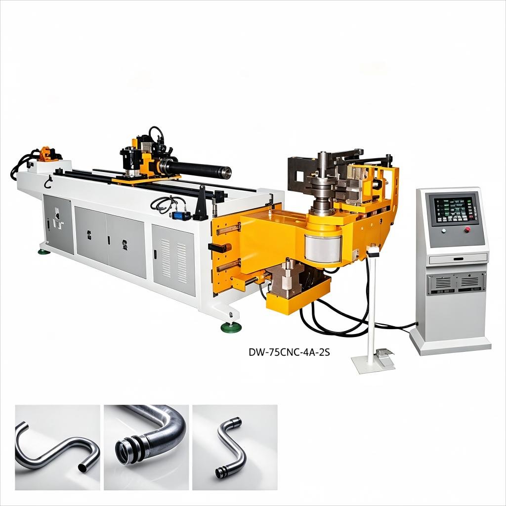
Jiuqiang manufactures NC, CNC, hydraulic and fully automatic tube bending machines for stainless steel, carbon steel, aluminum, copper and other metal tubes. The DW-75CNC tube bending machine is one example for automated metal tube production, but the machine and tooling should always be selected from the actual part.
Jiuqiang equipment is produced under ISO-certified quality procedures and supplied with CE certification. Machines are exported to Mexico, Vietnam and other countries. For a difficult bend, use the contact page to send the drawing and defect information rather than describing the problem only as “the tube wrinkles.”
Frequently asked questions
Can more hydraulic pressure remove wrinkles?
Sometimes a pressure correction helps, but excessive pressure can add drag, tooling marks or thinning. Inspect tool fit, mandrel position and the wiper die before increasing every setting.
Is a mandrel always required?
No. A thicker-wall tube or generous radius may bend without one. Thin walls, tight radii and strict ovality limits are more likely to need internal support.
Why does the first batch bend well but the next batch wrinkle?
Check actual wall thickness, mechanical properties, seam position and surface condition. A change in material can alter the process even when the purchase description is unchanged.
Should I change several settings at once?
No. Establish a baseline and change one controlled variable at a time. Measure and record each result so the cause remains visible.