Tube Plastic Forming Core Equipment: Tube Bending Machine – Classification, Forming Mechanism and Process Control System
News 2026-10-29
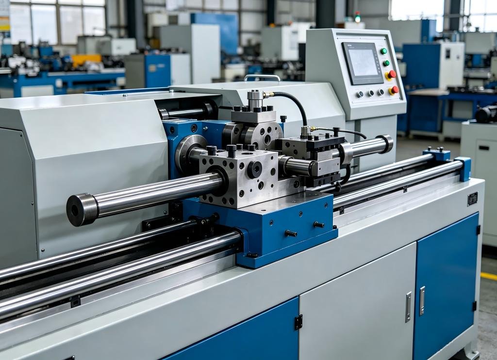
Within the pipeline engineering and metal tube processing industrial chain, tube bending machines are essential general-purpose equipment for plastic bending forming of tubes. They are widely adopted in power infrastructure construction, highway and railway projects, bridge building, shipbuilding, boiler supporting, furniture frame fabrication, architectural decoration and other scenarios, undertaking prefabricated pipeline laying, on-site modification and maintenance of various piping systems. Among them, hydraulic models feature a distinctive multi-functional design. Apart from standard tube bending operations, their oil cylinder can independently serve as a hydraulic jack for lifting tasks, integrating forming and auxiliary tooling functions. Compared with dedicated CNC tube bending machines, such multi-purpose models feature controllable costs and a low learning curve, adapting to diverse on-site working conditions and maintaining steady demand in the general tube processing market. Driven by the trend of standardization and prefabrication in pipeline engineering, tube bending equipment has evolved into a differentiated product portfolio, covering simple on-site fabrication and high-precision mass forming, and has become an irreplaceable foundational piece in the pipeline manufacturing ecosystem.
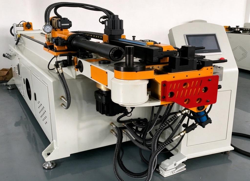
Classified by power structure, control mode and forming method, mainstream tube bending machines fall into four major categories: hydraulic electric tube bending machines, horizontal hydraulic tube bending machines, multi-functional rolling tube bending machines and digital display tube bending machines. Each category targets distinct application scenarios. Hydraulic electric models are optimized for fast on-site bending and lifting work; horizontal hydraulic variants are designed for heavy-duty forming of large-diameter and thick-walled tubes; rolling tube bending machines excel at continuous large-radius arc forming; digital display models add digital angle readouts on the basis of basic hydraulic structures to realize visual precision control. Higher-end CNC tube bending machines adopt digital control systems, lifting equipment precision, consistency and flexible processing capacity to a new level, making them the primary choice for mass production of precision tubular components.
The structural design of CNC tube bending machines is built around stable forming, convenient programming and rapid fault troubleshooting. Equipped with a touchscreen human-machine interface and CNC modules, they support conversational programming. The setup of process parameters and machining programs is intuitive and straightforward, lowering the programming barrier for operators. The thickened and reinforced one-piece machine bed delivers sufficient rigidity and resists deformation under long-term bending loads to guarantee stable reference datum. Independent parameters can be configured for each gear. Up to 16 bending angles can be preset per gear, and the built-in memory can store 16 separate machining programs for instant recall of different tube recipes. The machine features slow positioning to buffer impact during tube feeding, delivering stable bending angles with a repeat accuracy of ±0.1°. When program conflicts, parameter overruns or mechanical abnormalities occur, fault codes and prompts pop up directly on the screen to help operators locate and resolve issues quickly. In addition, proprietary coordinate conversion algorithms are integrated to output bending parameters directly. Optional calculation software can be installed on desktop terminals for tube unfolding, coordinate conversion and process simulation in advance to verify the feasibility of forming schemes.
The plastic deformation principle of tube bending shares the same physical logic as sheet metal bending. Under pure bending conditions, for a tube with outer diameter D and wall thickness t subjected to external bending moment M, the outer wall on the neutral layer is under tensile stress and becomes thinner, while the inner wall on the neutral layer bears compressive stress and thickens. Under combined forces, the originally circular cross-section transforms into an approximate ellipse. If deformation exceeds the material tolerance limit, cracks or fractures will appear on the outer tensile zone, and wrinkles will form on the inner compression zone, resulting in scrapped workpieces.
The degree of tube deformation is determined by two key dimensionless parameters: relative bending radius R/D and relative wall thickness t/D. Smaller values of R/D and t/D correspond to greater deformation and higher forming risks. To consistently ensure finished tube quality, deformation must be kept within the allowable forming range of the material. The forming limit of tube bending is not a single indicator. It requires comprehensive consideration of material mechanical properties, bending processes and service requirements of finished tubes. Four core control criteria are included: first, the maximum elongation in the outer tensile zone of the neutral layer must not exceed the material plastic limit to prevent cracking; second, the thin-walled section in the inner compression zone of the neutral layer must avoid buckling and wrinkling under tangential compressive stress; third, cross-section distortion must be restricted for precision tubes with ellipticity requirements; fourth, wall thinning must be controlled for pressure-bearing tubes to maintain structural strength under internal pressure.
Beyond equipment selection and material limit control, standardized pipeline design at the preliminary stage is critical to reduce forming defects and accommodate automated production. During tube shape planning and pipeline layout, structures that hinder bending should be avoided, including oversized arcs, irregular free curves, complex multi-directional compound bends and arcs exceeding 180°. Oversized arcs require bulky tooling and are limited by machine travel dimensions. Irregular curves and complex compound bends are not suitable for continuous mechanized production and rely heavily on strenuous manual work. Bends greater than 180° make it impossible to demould the finished tube after forming.
Standardization of bending radius is a core rule for modular pipeline design. The industry widely follows two principles: “one tube, one die” and “multiple tubes, one die”. “One tube, one die” means that regardless of the number of bends and bending angles on a single tube, only one bending radius is adopted throughout the process without die changes, eliminating errors and downtime caused by die switching. “Multiple tubes, one die” means tubes of the same outer diameter should preferably adopt the same bending radius. The same set of dies can produce tubular parts of different shapes, drastically reducing the number of dies, lowering tooling costs and shortening changeover time.
The selection of bending radius directly determines the resistance encountered during forming. Industrial experience shows that large-diameter tubes paired with an excessively small bending radius are prone to inner wrinkling and slipping, making stable quality hard to achieve. For general applications, the recommended bending die radius R is 2–3 times the tube outer diameter, balancing forming difficulty, layout space and mechanical performance of the tube.
Bending speed is a frequently overlooked parameter that greatly impacts finished quality. Excessively fast forming speed flattens the bent section, fails roundness requirements, and may even tear the tube. Too slow speed increases wrinkling risk and slippage between clamping blocks and the tube; large-diameter tubes may sag in the bent area. Extensive tests on CNC tube benders have proven that the optimal bending speed for balanced productivity and yield is 20%–40% of the machine’s maximum speed.
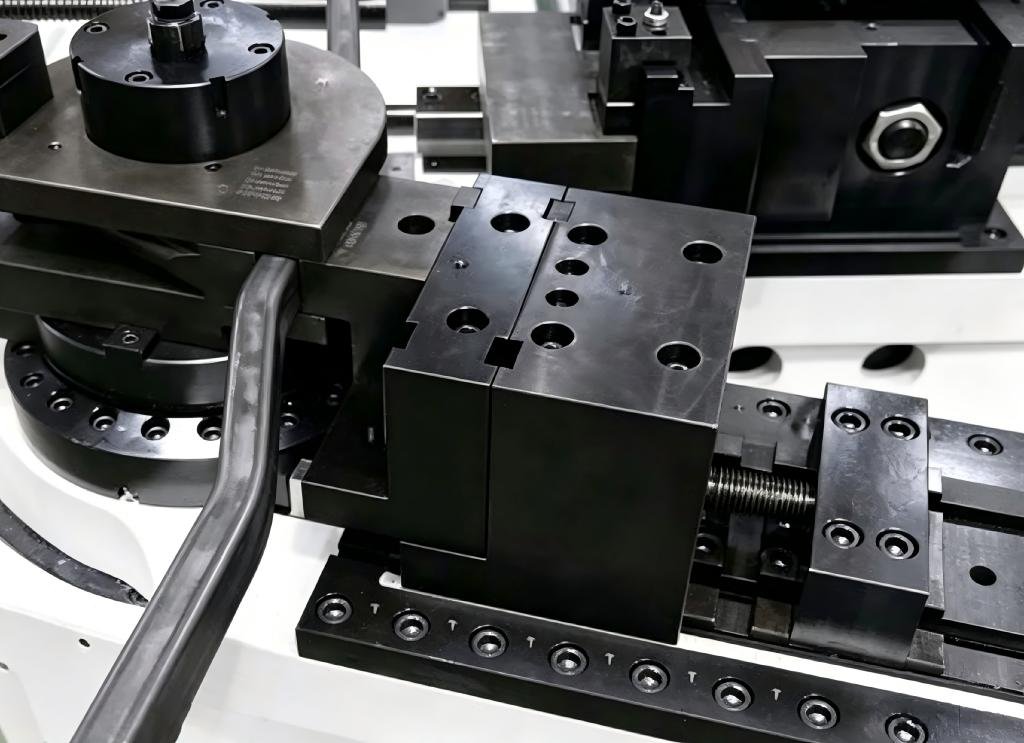
Mandrels are vital auxiliary components for forming thin-walled tubes with small bending radii. Inserted inside the tube, they support the inner wall of the bending zone to restrain cross-section collapse and elliptical deformation. For domestically produced tubes, high yield rates for thin-walled bending are difficult to guarantee without mandrels. Mandrels come in a wide range of types, including solid mandrels, universal single-ball, double-ball, triple-ball, four-ball mandrels, and directional single-ball and multi-ball mandrels, which can be selected according to tube diameter, wall thickness and bending radius. The axial position of the mandrel also significantly affects forming results. Theoretically, the mandrel tangent should align with the bending die tangent. However, abundant process tests show that shifting the mandrel forward by 1–2 mm delivers optimal forming quality. Excessive forward offset will create a typical “goose neck” defect on the outer wall of the bent section, rendering the tube non-conforming.
Looking ahead, the wave of pipeline prefabrication and digital manufacturing continues to drive innovation of tube bending equipment. Traditional multi-purpose hydraulic models remain popular for site work thanks to cost-effectiveness and multi-scenario functionality. CNC precision bending systems are advancing toward process simulation, in-line dimensional inspection and adaptive springback compensation. These systems predict wrinkling, collapse and interference risks in advance, automatically adjust springback values and reduce manual trial bending. Meanwhile, new tube materials such as high-strength alloys and precision thin-walled tubes are gaining popularity, pushing continuous upgrades of bending processes, die materials and mandrel solutions. As foundational equipment for pipeline forming, tube bending machines will keep supporting industries including infrastructure, shipbuilding, boiler manufacturing and furniture production, advancing pipeline processing toward standardization, low material loss and high yield.