How to Prevent Wrinkles in Tube Bending: Causes and Practical Solutions
News 2026-09-12
A wrinkled bend is more than a cosmetic problem. Ripples on the inside of a tube bend can reduce flow, interfere with assembly, create stress concentrations and make an otherwise usable component fail inspection. In production, the cost is not limited to one rejected tube. Operators lose time adjusting the machine, material is wasted, and delivery schedules become harder to control.
The good news is that wrinkling is usually a process problem with an identifiable cause. It can often be corrected by checking the relationship between the tube, bend radius, tooling and machine settings in a logical order. This guide explains why wrinkles form, how to diagnose them and what practical adjustments usually produce a clean bend.
What causes wrinkles during tube bending?
During bending, the material on the outside of the bend is stretched while the material on the inside, known as the intrados, is compressed. If the compressed wall cannot remain stable, it moves sideways and forms waves. Thin-wall tubing, small centerline radii and materials with inconsistent mechanical properties are especially sensitive.
Wrinkling should not be confused with flattening. Flattening changes the round tube into an oval shape across the bend. Wrinkles appear as repeated ridges, normally on the inside radius. Both defects can occur at the same time, but they are controlled by different combinations of tooling and settings.
Before changing the machine, record the tube outside diameter, wall thickness, material grade, hardness, weld seam position, centerline radius and bend angle. Also note where the first wrinkle appears. A wrinkle that starts immediately after the tangent point often points to mandrel or wiper-die setup. Wrinkles distributed through the entire bend may indicate insufficient pressure-die support, an unsuitable radius or excessive compression.
1. Check whether the bend radius is realistic
A tight bend places much more compression on the inside wall than a large-radius bend. One useful starting measurement is the D ratio: centerline radius divided by tube outside diameter. A low D ratio means the job is demanding. Wall factor, calculated from outside diameter divided by wall thickness, is also important. A tube with a high wall factor has a relatively thin wall and needs better internal support.
There is no single minimum radius that works for every material. Stainless steel, aluminum and copper alloys behave differently, and even tubes with the same nominal dimensions may vary by heat treatment or supplier. If the drawing permits a slightly larger centerline radius, that change may solve wrinkling more reliably than increasing pressure throughout the machine.
When the radius cannot be changed, plan to use a correctly sized mandrel, an accurately fitted wiper die and stable pressure-die assistance. Trying to make a very tight bend with simple tooling normally leads to repeated adjustments and inconsistent parts.
2. Select the right mandrel and set its position
The mandrel supports the tube from inside as it enters the bend. A plug mandrel may be enough for heavy-wall tubing and generous radii. Thin-wall or tight-radius work commonly requires a ball mandrel, because the articulated balls support the tube farther around the arc.
Mandrel size matters. Excessive clearance allows the tube wall to move before the tooling can control it. Too little clearance increases drag, produces scratches and can make loading or extraction difficult. Tooling clearance should be based on the actual tube dimensions, not only the nominal size printed on a purchase order. Measuring several samples with a micrometer is a small step that prevents hours of troubleshooting.
Position is equally important. As a practical starting point, the mandrel nose is placed near the tangent point and then adjusted in small increments. If it sits too far back, the inside wall loses support and wrinkles can begin near the start of the bend. If it is advanced too far, the tube may drag, tear, mark or become difficult to release. Move the mandrel a small distance at a time, make one test bend and record the result before changing another parameter.
3. Inspect and adjust the wiper die
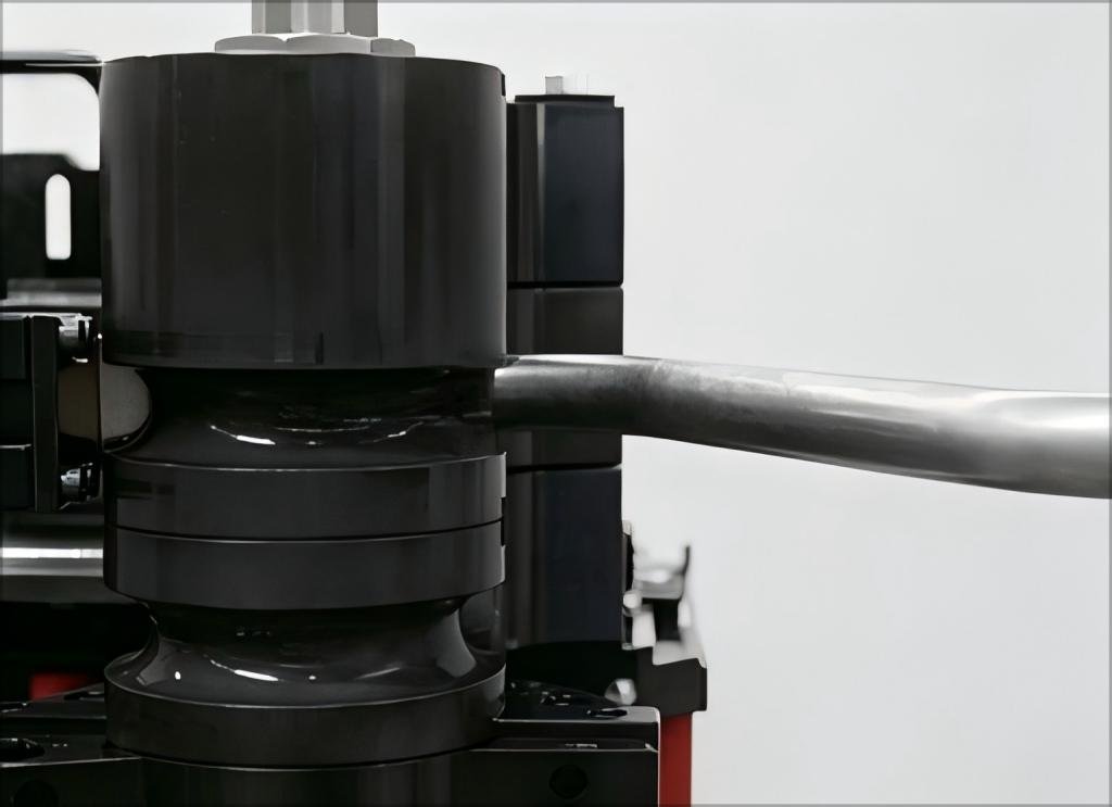
The wiper die controls the compressed material directly behind the bend-die tangent. Its thin tip fills the gap where the tube would otherwise buckle. For demanding bends, a correct wiper die is often the difference between a smooth intrados and a row of deep wrinkles.
Check that the wiper-die groove matches the tube and bend die. The tip should be sharp enough to provide support, but it must not be chipped or feathered to the point that it breaks. The die should sit in the correct vertical position without twisting. A visible gap between the wiper die and bend die reduces its ability to control the wall.
Do not assume that pushing the wiper die farther forward always improves the bend. Excessive advance can cause galling, tool marks and premature wear. Set it according to the tooling maker’s reference, then adjust gradually. If a previously stable job begins to wrinkle without any program change, inspect the wiper tip for wear before increasing machine pressure.
4. Verify clamp-die and pressure-die support
The clamp die must hold the tube firmly enough to rotate it with the bend die. If the tube slips, material feed becomes unpredictable and defects can appear near the tangent. Look for polished slip marks on the clamped section and compare the actual bend angle with the programmed angle.
The pressure die supports the straight section of tube as it moves toward the bend. Insufficient pressure allows the tube to lose contact and buckle. Excessive pressure increases friction and can stretch or mark the part. On machines equipped with pressure-die assist, the assist motion should be synchronized with the tube’s movement around the bend. Too little assist may contribute to wall thinning and drag; too much can push material into the bend and create instability.
Always confirm that tooling faces are clean. Chips, dried lubricant and small pieces of scale can change the effective clamping force and leave dents that look like process defects. Cleaning the dies between batches is faster than compensating for contamination with higher hydraulic pressure.
5. Control material variation
A bending program proven on one batch may not produce the same result on another. Actual wall thickness, yield strength, elongation, hardness and weld quality can all change the way the tube compresses. Welded tubing may also bend differently depending on seam orientation.
For repeat production, keep material certificates and identify each batch. Measure outside diameter, wall thickness and ovality before loading a new lot. Run a first-piece inspection rather than sending the entire batch through an old program. If possible, agree on tighter mechanical-property and dimensional tolerances with the tube supplier. Consistent incoming material reduces the amount of machine compensation required.
Seam placement should also be controlled. The best orientation depends on the material, radius and part geometry, but random seam position introduces another variable. Mark the seam during trials and record the orientation that produces the most stable bend.
6. Use the correct lubricant in the correct amount
Lubrication reduces friction between the tube, mandrel and wiper die. Without enough lubricant, the tube may drag over the tooling, increasing heat and making the material flow unevenly. Too much lubricant, however, can contaminate clamps, reduce grip and create cleaning problems after bending.
Choose a lubricant compatible with the tube material and the customer’s downstream process. Stainless steel generally needs a high-performance lubricant that can withstand pressure without causing galling. Aluminum surfaces scratch easily and may require a cleaner, material-compatible product. Parts intended for welding, painting or medical service may have strict residue requirements.
Apply lubricant consistently rather than relying on an operator’s estimate. For repeated work, a controlled lubrication system makes the process easier to reproduce. If clamp slippage appears after lubrication changes, clean the clamp area and make sure lubricant is reaching only the surfaces that need it.
7. Reduce speed only after the tooling is correct
Bend speed affects material flow, particularly on thin-wall tubing and long bends. Slowing the bending motion can reduce sudden loading and give the tooling more time to control the wall. It is a useful adjustment, but speed should not be used to hide a worn wiper die or incorrectly positioned mandrel.
On CNC tube bending machines, check the coordination between feeding, rotation, clamping, pressure-die assist and mandrel extraction. The extraction point is especially important. Pulling the mandrel too early removes support before the bend is complete; pulling it too late can score the tube or lock the part on the tooling.
Change one setting at a time. A simple trial sheet should record program version, material batch, tooling set, mandrel position, pressures, assist value, bend speed and inspection results. This habit makes a stable process transferable between operators and shifts.
A practical troubleshooting sequence
- Confirm that the correct tube, tooling set and program have been loaded.
- Measure the actual tube diameter, wall thickness and ovality.
- Clean the bend die, clamp die, pressure die, mandrel and wiper die.
- Inspect the wiper tip and mandrel balls for wear, looseness or damage.
- Check clamp grip and look for evidence of tube slippage.
- Set the mandrel and wiper die to their recorded reference positions.
- Verify pressure-die contact and assist synchronization.
- Confirm lubricant type, amount and application point.
- Make one test bend at a conservative speed.
- Adjust only one parameter, document it and repeat the test.
This sequence prevents random adjustment. Increasing several pressures and changing the mandrel position at the same time may produce one acceptable piece, but nobody will know which change solved the problem or whether the process will remain stable.
How Jiuqiang supports stable tube bending
Jiuqiang manufactures CNC, hydraulic, fully automatic and semi-automatic tube bending machines for metal tube applications. Available solutions cover materials including mild steel, stainless steel, aluminum, copper and aluminum profiles. Depending on the selected model and application, the product range can handle tube diameters up to 114 mm and wall thicknesses up to 10 mm.
Because bending results depend on more than the machine itself, application review should begin with the part drawing and tube specification. Jiuqiang can evaluate bend radius, material, diameter, wall thickness, number of bends, required accuracy and production volume before recommending a machine and tooling arrangement. Supplying sample parts or tube material for a bending trial is particularly useful when the bend is tight or the surface finish is important.
Jiuqiang products are supported by CE certification and ISO quality management certification. Machines have been supplied to international markets including Mexico and Vietnam, serving applications such as automotive components, exhaust systems, furniture, shipbuilding and general metal fabrication. Documentation, operating guidance and remote technical communication help customers establish repeatable programs after installation.
Conclusion
Preventing wrinkles in tube bending is a matter of controlling compressed material on the inside of the bend. Start with a realistic bend radius and consistent tube specification. Then check the mandrel, wiper die, clamp die and pressure die before changing speed or pressure. Clean tooling, suitable lubrication and disciplined trial records turn a difficult bend into a repeatable production process.
If you are evaluating a new tube bending application, send Jiuqiang the tube drawing, material grade, outside diameter, wall thickness, bend radius and expected production volume. A complete application review makes it possible to select the appropriate machine capacity and tooling before production begins.