How to Prevent Wrinkles When Bending Stainless Steel and Aluminum Tubes
News 2026-09-04
Wrinkles, flattening, cracks, excessive wall thinning, and tool marks are among the most common reasons a bent tube is rejected. These defects become more difficult to control when a part uses stainless steel or aluminum, a thin wall, a small bending radius, or several bends close together. The problem is rarely solved by changing one machine parameter at random. Reliable improvement begins with identifying where material is under compression or tension and then checking the tube, tooling, lubrication, and bending program as one system.
This practical guide explains why bending defects occur and how manufacturers can reduce them when processing stainless-steel and aluminum tubes.
What Happens to a Tube During Bending?
During bending, the outside wall of the tube stretches while the inside wall compresses. The neutral area between them changes less. If the outside wall cannot elongate enough, it may thin excessively or crack. If the inside wall cannot remain stable under compression, it may form waves or wrinkles. At the same time, the round cross-section tends to become oval.
The severity of these effects depends on the relationship among tube diameter, wall thickness, and centerline radius. A thin-wall tube bent to a tight radius is generally more challenging than a thick-wall tube bent to a generous radius. Material strength, elongation, temper, weld seam, tooling clearance, lubrication, and machine rigidity also influence the result.
Why Stainless Steel Requires Careful Control
Stainless steel is widely used for exhaust systems, marine parts, fluid lines, food equipment, and architectural components because of its strength and corrosion resistance. However, it often requires greater bending force than mild steel and can show significant springback. Its surface can also be damaged by dirty tooling or unsuitable contact materials.
Material grade matters. Austenitic stainless steels and other grades do not respond identically. Tube manufacturing tolerances and work hardening also affect bending. When incoming batches vary, a program that worked well last month may need adjustment. Recording the material heat or batch, actual wall thickness, and springback correction can help separate material variation from machine problems.
Cleanliness is especially important. Chips, rust particles from carbon-steel processing, or damaged die surfaces can scratch the tube and contaminate stainless material. Dedicated or carefully cleaned tooling and correct lubricant are valuable when appearance or corrosion performance is critical.
Why Aluminum Behaves Differently
Aluminum offers low weight and good corrosion resistance, making it useful for transportation, furniture, heat-exchange, and structural applications. Yet aluminum tube can be sensitive to surface marking and cracking, particularly in harder tempers or when the requested radius is too tight for the alloy and wall thickness.
Not all aluminum tubes can achieve the same radius. Alloy, temper, extrusion quality, profile geometry, and seam condition should be confirmed. An aluminum profile with several internal chambers is a different forming problem from a round tube. Before production tooling is approved, a sample trial should use the actual extrusion or tube supplied for the project.
Tool surfaces may need polishing, coating, or non-marking inserts depending on the finish requirement. Lubricant must be compatible with the alloy and with any later welding, coating, or cleaning process.
Cause 1: Incorrect or Incomplete Tooling
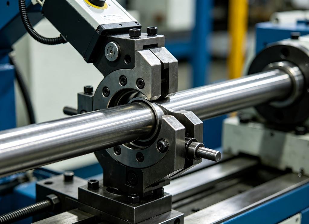
In rotary-draw bending, the main tooling normally includes a bend die, clamp die, and pressure die. More demanding thin-wall or tight-radius parts may also require a mandrel and wiper die. Each tool has a specific function.
- The bend die establishes the bending radius and supports the tube around the bend.
- The clamp die holds the tube and transfers pulling force without slipping.
- The pressure die supports the straight tube as it moves forward.
- The mandrel supports the inside of the tube near the tangent area.
- The wiper die helps prevent inside-wall material from forming a wrinkle.
If the bend die groove does not match the tube, if the clamp surface slips, or if the wiper tip is worn and positioned incorrectly, parameter adjustments alone will not create a stable process. Tooling should be designed from the actual tube dimensions rather than only nominal values.
Cause 2: Mandrel Position Is Wrong
A mandrel positioned too far behind the tangent point may not support the tube when it is most vulnerable to collapse. A mandrel too far forward can create drag, marking, breakage, or other distortion. The correct position depends on the tube, radius, mandrel design, and material.
Operators should adjust in controlled steps and record the result. Moving several settings at the same time makes it difficult to identify the true cause. Inspect the mandrel balls, links, and nose for wear or damage. For stainless steel, lubrication and surface condition become particularly important because forming loads can be high.
Cause 3: The Wiper Die Is Worn or Misaligned
The wiper die sits close to the bend-die tangent and controls the compressed material on the inside of the bend. Its tip must be thin, properly supported, and accurately positioned. A worn or poorly fitted tip leaves space for a wrinkle to form. An overly aggressive setting may increase friction or damage the tube.
Wiper dies are wear items. A preventive inspection plan is better than waiting until scrap rises. Check fit, tip condition, mounting rigidity, and alignment whenever a process that was previously stable begins to wrinkle.
Cause 4: Insufficient Clamping or Tube Slippage
If the tube slips during the bend, the programmed movement and the actual material movement are no longer the same. Slippage can cause angle errors, wrinkles, surface marks, and inconsistent straight lengths. Possible causes include inadequate clamp length, worn clamp surfaces, incorrect pressure, contamination, or an unsuitable clamping pattern.
Simply increasing clamp pressure is not always correct. Excessive pressure may crush or mark a soft aluminum tube. The goal is secure, repeatable holding with acceptable surface contact.
Cause 5: Pressure-Die Settings Do Not Support Material Flow
The pressure die supports the tube as it is drawn around the bend die. Depending on the machine and process, pressure-die assistance can help feed material and reduce outside-wall thinning. Incorrect pressure or movement may allow instability or create excessive drag.
Review pressure-die alignment, contact length, force, and assist settings where available. The setting should be developed together with mandrel and wiper position, not treated as an isolated number.
Cause 6: Lubrication Is Missing or Unsuitable
Lubrication reduces friction between the tube and internal tooling. Too little lubricant can produce drag, heat, tool wear, and surface damage. Too much lubricant creates housekeeping problems and may interfere with later operations. The wrong product may stain aluminum or be difficult to remove before welding.
Use a lubricant recommended for the material and downstream process. Apply it consistently in the correct location. A stable application method is more repeatable than relying on an operator to estimate the amount by sight.
Cause 7: Material or Tube Dimensions Are Inconsistent
A bending process cannot compensate indefinitely for inconsistent input. Measure actual outside diameter, wall thickness, ovality, hardness, and weld-seam behavior when defects vary between batches. For extruded aluminum profiles, check dimensional consistency and internal geometry. For welded tubes, maintain a consistent seam orientation if the application requires it.
Incoming inspection does not need to be complicated. A small record of critical tube measurements and the corresponding bend result can reveal patterns that are otherwise blamed on the machine.
How to Reduce Flattening and Ovality
Flattening occurs when the cross-section loses its intended shape. A mandrel, correct bend-die groove, suitable radius, and proper pressure-die support can reduce ovality. The required solution depends on the customer’s acceptance standard. A decorative furniture tube, an exhaust tube, and a high-pressure fluid component may have very different limits.
Define ovality numerically and measure at a consistent location. If the part is checked only by visual judgment, different inspectors may reach different conclusions. For very demanding components, cutting and measuring development samples can show wall thinning and cross-sectional change.
How to Control Cracking and Excessive Thinning
Cracking on the outside of the bend can indicate an unsuitable radius, insufficient material elongation, poor tube quality, a hard material condition, or excessive stretching. Outside-wall thinning is influenced by radius, wall factor, tooling, pressure-die assistance, and process settings.
If the drawing allows it, increasing the centerline radius is often the most direct improvement. If the radius cannot change, review material temper, tube specification, tooling support, and process feasibility with the machine supplier. Do not accept a visually successful trial without checking minimum wall thickness when the component has structural or pressure requirements.
A Systematic Troubleshooting Sequence
When a defect appears, use a repeatable sequence:
- Identify the exact defect and its location on the bend.
- Confirm the correct program, tooling set, and material batch.
- Measure actual tube diameter and wall thickness.
- Inspect bend, clamp, pressure, mandrel, and wiper tools for wear or contamination.
- Verify tooling alignment and lubrication.
- Change one parameter at a time and record the result.
- Measure the successful part against the agreed acceptance criteria.
- Save the final parameters and setup notes for repeat production.
This approach reduces guesswork and helps different operators reproduce the same result.
Choosing a Machine for Difficult Materials
A suitable tube bending machine should provide adequate rigidity, repeatable motion, appropriate tooling space, and controllable functions for the intended part. CNC control is valuable for multi-bend components and frequent repeat production. Hydraulic and semi-automatic equipment may be economical for simpler geometries and lower volumes. Fully automatic systems can add feeding, rotation, loading, unloading, and integration for mass production.
Suzhou Jiuqiang Machinery Technology Co., Ltd. supplies CNC, hydraulic, fully automatic, and semi-automatic bending solutions for stainless steel, iron, aluminum, copper, aluminum profiles, and other metal tubes. Available solutions can be evaluated for applications up to 114 mm outside diameter and wall thicknesses up to 10 mm, subject to material, radius, and part review.
Conclusion
Wrinkle-free tube bending is the result of a balanced process, not one “perfect” setting. The tube specification, radius, bend method, machine, tooling, lubrication, and inspection standard must agree. Stainless steel requires attention to force, springback, cleanliness, and galling. Aluminum requires careful review of alloy, temper, surface finish, and support.
For a reliable recommendation, send the engineering team a part drawing, material grade, tube dimensions, required output, and acceptable limits for ovality, wall thinning, and surface marks. Sample testing with actual production material is the clearest way to confirm the machine and tooling configuration before full production.