Stainless Steel Tube Bending Machine: Holding Springback, Thinning and Galling Inside One Process Window
News 2026-11-13
1. Why Stainless Steel Is the Honest Judge of a Bending Shop
A carbon steel tube that comes out wrong can be patched, welded or ground back into shape. A stainless tube that comes out wrong usually goes into the scrap bin. The reason is not price. It is the material’s temperament.
Austenitic stainless steels work-harden quickly. Yield strength climbs as the section deforms, the yield-to-tensile ratio stays high, and the elastic recovery after unloading is far more pronounced than in low-carbon steel. Its elastic modulus is not especially high — roughly 190 GPa at room temperature, within ten percent of carbon steel — but its yield strength can be two or three times higher. Put those two numbers together and the springback amplifies accordingly. On the same tooling and the same program, a carbon steel tube may bend to nominal in one pass, while a stainless tube lands two or three degrees off and the mismatch only shows up at assembly.
Poor thermal conductivity is the second problem. Friction heat generated during bending concentrates in the contact band between tooling and tube wall. It cannot dissipate quickly, and once the lubricating film breaks down the contact changes from sliding to adhesion. The result is galling: smeared scratches, sometimes pick-up severe enough to seize. On carbon steel such marks can be dressed out afterwards. On a polished stainless surface, one galled patch scraps the whole part.
The third problem is that stainless surfaces are unforgiving. Brushed grain, mirror finish, polished bore — any dent, scratch or fingerprint stays visible. Bending is often scheduled after polishing and before assembly, which makes it the last operation that is allowed to go wrong.
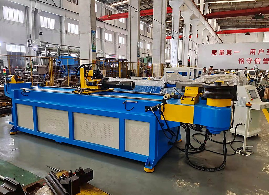
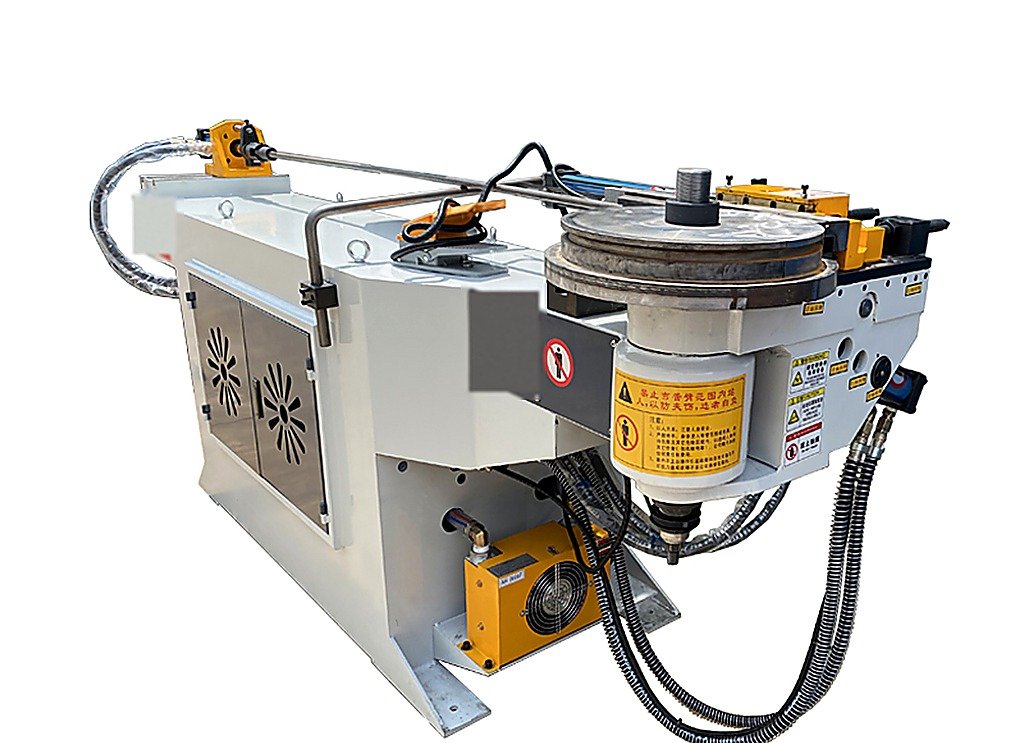
The significance of a stainless steel tube bending machine therefore is not whether it can force a tube around a die. It is whether the part that comes out still behaves like a part.
2. What Actually Happens Inside a Single Bend
Pressing a tube around a bend die looks like one motion. Inside the section, four things happen at once.
The wall outside the neutral axis is stretched and thins. The wall inside the neutral axis is compressed and thickens, and once the compressive stress exceeds the stability limit of a thin wall, the inner radius starts to wrinkle. The circular section flattens under the bending moment, with the major axis in the plane of bend — ovalization. And at the moment the die opens and the clamp releases, the elastic portion of the deformation recovers: the finished angle is smaller than the commanded angle, and the finished radius is larger than the die radius.
These four effects constrain each other, and that is where the difficulty lives. Push the wiper die harder and advance the mandrel to suppress inner wrinkling, and friction rises, which increases wall thinning and galling risk. Over-bend to compensate springback and the angle overshoots; under-compensate and the part will not fit. Tighten mandrel support to control ovality, and feed resistance climbs until a thin-wall tube buckles in the feed section.
Setup, in other words, is the search for the one standing position left in a room with four walls. It also explains why identical machines produce first-time-right parts in one shop and thirty percent scrap in another.
3. Springback: The Most Honest Form of Resistance
Springback is not random. It follows fairly clear rules. Within normal bend angles, springback angle varies almost linearly with bend angle. The larger the relative bend radius R/t, the larger the springback. The higher the material yield strength, the more pronounced the recovery.
Material substitution is where this hurts most. The gap between 304 and 316L is moderate. Switch to a duplex grade such as 2205, whose yield strength is roughly twice that of 304, and springback rises sharply — the entire compensation table becomes invalid. Even within 304, the difference between solution-annealed and cold-worked condition is enough to shift the finished angle by more than a degree.
The engineering answer has three steps. First, trial bends: three to five parts on the same material lot, same tooling, same lubrication, with angle and radius measured and deviations recorded. Second, build the table: map springback compensation against bend angle, write it into the program so the controller adds the correction at every bend. Third, re-verify: after a lot change, a wall thickness shift within tolerance, or a die regrind, run trial bends again and recalibrate.
Some shops still treat springback as operator feel — tap it, shim it, try again. That works for single-variety, low-volume work. It collapses on multi-bend spatial parts, tube-to-flange joints and welded assemblies, where errors accumulate. Half a degree at each of six bends can become more than ten millimeters of misalignment at the last end.
There is a subtler characteristic worth naming: stainless springback is extremely sensitive to wall thickness deviation. Cold-rolled welded tube typically carries a wall tolerance of around plus or minus ten percent. Within one lot, the thinner sections spring back noticeably more than the thicker ones. That is why some batches run eight good parts and two bad ones. The machine is fine. The incoming material is not uniform.
4. The Mandrel: The Bone You Cannot See
In thin-wall bending, success largely depends on the tool inside the tube.
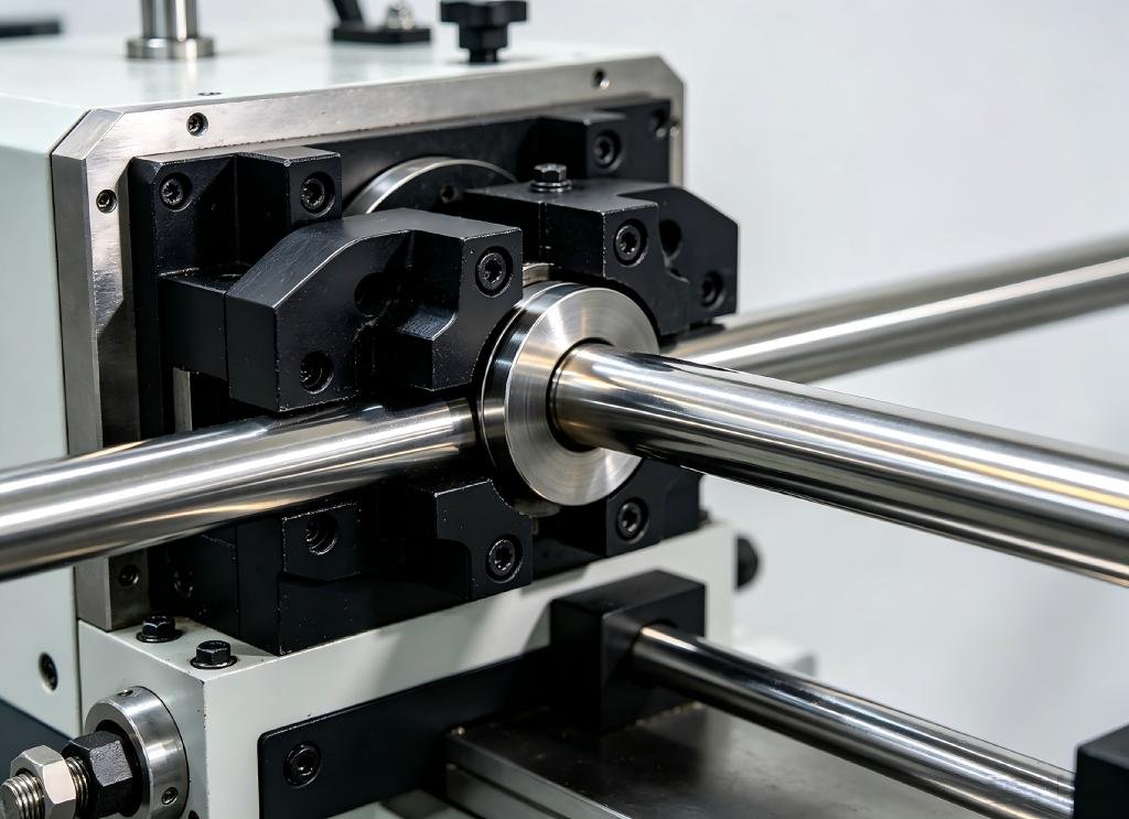
Five mandrel constructions are common: cylindrical, round-nose, arc, ball-and-socket, and round-nose ball-and-socket. The first three are solid-body types. They are stiff and support the tube continuously, which favors control of outer wall thinning; the arc type performs best at reducing thinning. The last two are articulated, built from a mandrel shank connected to a series of balls by spherical joints or an elastic element, so the assembly deflects progressively through the bend. They have the highest conformability and the strongest ability to suppress inner wrinkling. Taking overall forming quality as the criterion, the ball-and-socket type is usually the balance point: it holds wrinkles back without pulling the outer wall too thin.
Selection logic is not complicated. With a generous R/t and adequate wall, a plain mandrel, a round-nose mandrel, or even bending without a mandrel can be sufficient. Below R/t of about 2, or when wall thickness falls under roughly two percent of outside diameter, an articulated mandrel plus a wiper die is effectively mandatory — otherwise the inner radius will wrinkle. Because stainless work-hardens fast, it needs continuous support at R/t values where carbon steel would still be comfortable.
The hard variable is mandrel advance, the position of the mandrel nose relative to the tangent point. Too far back and the inner bend loses support, so wrinkling starts at the bend point and spreads. Too far forward and the nose presses into the wall: thinning rises and ring-shaped marks appear on the bore. The measured pattern is consistent — as advance increases, ovality first decreases and then increases, so there is a clear optimum window. It has to be re-found for each wall thickness and each R/t, and the usual acceptance is the position where three conditions hold at once: no visible inner wrinkle, thinning inside the acceptance limit, minimum ovality.
Mandrel diameter, number of balls, ball pitch and ball thickness determine how continuous the support is. Too few balls leave unsupported spans, and wrinkles form exactly there. Too many, packed too tightly, raise bending resistance until a thin wall buckles. These parameters are normally frozen at tool design stage; what the shop can adjust on the floor is advance and lubrication.
One detail is regularly overlooked: the condition of the mandrel surface itself. A scored, built-up or pick-up mandrel prints its defects directly onto the bore. One scratch on the tool becomes one gall line on the part. Mandrels need periodic polishing and straightness checks, and they must not be knocked about during extraction.
5. Wiper Die, Clamp Die and the Bend Point
The wiper die holds the inner wall at the tangent point and prevents material from extruding into the die gap. Its radius must match the bend die closely. If the gap is too large, material has somewhere to go and the wrinkle forms anyway. If it is too tight, friction rises and a thin wall is dragged thinner, sometimes to tearing.
Clamp die pressure matters just as much. Insufficient pressure lets the tube slide axially at the instant the bend starts, which changes the straight length of the first leg and squeezes material near the bend point. Excessive pressure leaves clamp marks, most visible on mirror finishes. For brushed and polished tube, soft wiper dies in nylon, polyurethane or copper-based alloy are close to mandatory, because a mark from a hardened die cannot be repaired.
The bend point is another frequent failure. It defines the actual length of every straight leg, and a wrong straight length means the part will not fit. Accurate cut length requires three allowances to be calculated together: the tangent-point compensation, which is the length the material draws into the bend; the arc-length change caused by springback; and the process allowance needed for clamping and feeding. Hand calculation can work for small batches. Multi-bend spatial parts need software that converts tube geometry directly into a compensated program.
6. Thinning and Ovality: Numbers That Belong on the Inspection Sheet
Process discussion has to land on measurable criteria, otherwise it stays at “looks acceptable”.
For cold-formed fittings, maximum wall thinning is generally held to about twelve percent, per the relevant steel butt-welding fitting standard. For welded stainless steel tube used in fluid conveying, the bending thinning limit is around fifteen percent. Outside diameter deviation after bending is usually required to stay within plus or minus five percent. For conveying piping, within one hundred millimeters of the tube end the difference between maximum and minimum outside diameter should not exceed 5.6 mm. Pressure-containing fittings carry separate wall thickness and ovality requirements under butt-welding fitting standards.
These figures are the pass line, not the target. Real drawings are usually stricter: thin-wall exhaust components may call for thinning under ten percent; hygienic piping adds requirements that bore roughness must not degrade and that no residue remains. Which is why the first document for a bending job should not be the program. It should be a process card listing material, R/t, wall thickness, maximum thinning, maximum ovality and surface grade.
7. The Weld Seam: The Most Overlooked Variable in Welded Tube
When welded tube is bent, the seam is a band where microstructure and stress are discontinuous. Its ductility, hardness and residual stress differ from the parent metal, so its behavior under bending differs too.
Standard practice keeps the seam away from the most severely deformed zones — the extreme outer fiber, which is in maximum tension, and the extreme inner fiber, which is in maximum compression — and places it near the neutral axis, typically at about forty-five degrees to the bend plane. Within a batch, seam orientation should also be kept consistent. Otherwise, on the same program, some tubes wrinkle and crack while others do not.
There is a hidden risk near the seam as well. Wall thickness often bulges or dips in the weld zone, so the clearance seen by the mandrel changes locally, and that is where marks or excess thinning tend to appear. For thin-wall welded tube it is worth confirming that weld reinforcement has been dressed flush before bending.
8. Cold Bending or Hot Bending
Stainless tube should generally be cold bent. Cold bending preserves surface quality and dimensional accuracy; the price is work hardening and springback. Hot bending, typically by medium-frequency induction heating in the range of 1100 to 1200 degrees Celsius, sharply reduces deformation resistance and allows smaller relative bend radii, but it brings oxide scale, color change and reduced corrosion resistance, and the part must cool slowly in still air afterwards — never be quenched with water.
The choice depends on R/t, wall thickness, surface grade and downstream operations. Where parts will be polished, passivated or electropolished afterwards, the oxide layer from hot bending is pure added cost. Where pressure is high, R/t is very small and the wall is heavy, hot bending is the more realistic route. Aluminium-manganese alloys are not permitted to be cold bent at all; that is a hard material constraint.
9. Surface: Stainless Finish Is Made, Not Repaired
Carbon steel scratches can be ground and repainted. Stainless offers no such recovery. So the discipline on a stainless bending line often centers less on machine parameters and more on cleanliness.
Tooling and mandrels must be clean. Iron chips, aluminium chips and hard particles left from a previous job act like abrasive paper under contact pressure, and one pass can draw a long scratch across a mirror surface. Lubrication between mandrel and bore must be adequate and even; the overwhelming majority of galling occurs along the contact band on the inner radius. Brushed and mirror sheets should stay under protective film through cutting, handling and bending, and parts should not be set on the floor or stacked on each other between operations. Laser or plasma cutting is preferred over sawing, because burrs pressed into the wall during bending become permanent marks.
For food, pharmaceutical and semiconductor piping there is an additional layer of requirement: no residue in the bore. Lubricant, metallic particles from mandrel wear, and cutting fluid that was not fully removed all become obstacles later in qualification. Such parts normally go through cleaning and passivation after bending, and that sequence has to be settled at quotation stage — adding it after the fact can double the cost.
10. What Has Changed on the Machine Side: From “Can Bend” to “Can Repeat”
The meaningful change in bending equipment over the past decade has not been tonnage. It has been controllability.
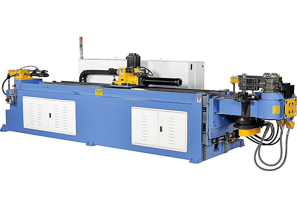
Servo drive has steadily displaced hydraulics. Feed axis, rotation axis and bend axis each run on independent servos, joined by boost and lift axes to form multi-axis interpolation. Feed accuracy and rotation accuracy directly determine accumulated error on multi-bend spatial parts, which is exactly where stainless work is most exposed — large springback means error will not disappear unless it is compensated.
At the control level, direct import of tube geometry has become standard. A three-dimensional tube model generates the program, runs interference checks and allocates bend sequence automatically, reducing dependence on individual operator experience. Laser tube cutting integrated with bending is also spreading: cut first, bend second, eliminating one clamping operation and one datum transfer, with end preparation and holes formed in a single setup.
Automated loading and in-line inspection address a different pain point. Stainless parts are surface-critical, and manual handling is itself a source of scratches. Robotic pick-and-place, dedicated racks and isolation between operations sometimes contribute more to yield than any parameter tweak.
But equipment can only deliver repeatability. Tooling defines the forming boundary, parameters define the process margin, and what actually decides whether a batch fits at assembly is process discipline: first-article inspection, locked parameters, recalibration after material change, and traceable records.
11. Locking the Process Window Down
A stainless bending process that stays stable over time usually runs as a closed loop.
First-article trial bending uses the same material lot, same tooling and same lubrication, producing three to five parts. Measure bend angle, bend radius, ovality, outer wall thinning, bend point position and straight leg lengths. Compare against drawing, then correct the springback compensation table and the cut-length compensation. Once parameters are locked, production begins with sampling of critical dimensions by lot. If dimensions drift, check incoming wall thickness and tool wear first, then lubrication and mandrel condition.
Process records should cover at minimum: material grade and delivery condition, measured wall thickness, R/t, mandrel type and advance, wiper die material and gap, clamp pressure, lubrication method, springback compensation values and bend point compensation values. The list looks tedious. It is also the only asset that carries over to the next material change.
12. Closing
Stainless tube bending is difficult because it puts four conflicts on the same table at once: springback must be compensated, thinning must be controlled, wrinkling must be suppressed, and surface must be preserved. Solving any one of them alone is not hard. Making all four hold inside a single process window is.
Equipment supplies repeatability, tooling sets the boundary, parameters leave the margin. What connects the three is an understanding of how the material behaves, and the patience to measure it. A cleanly bent stainless tube is rarely the product of one particularly advanced machine. It is the product of a process discipline that has been calibrated over and over.