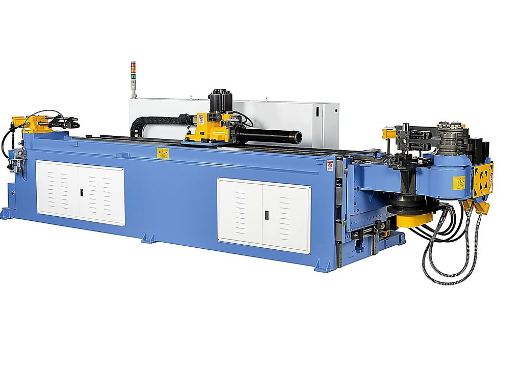
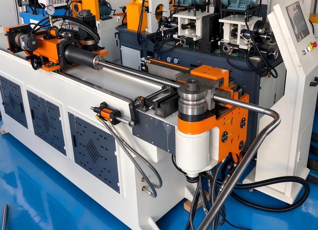
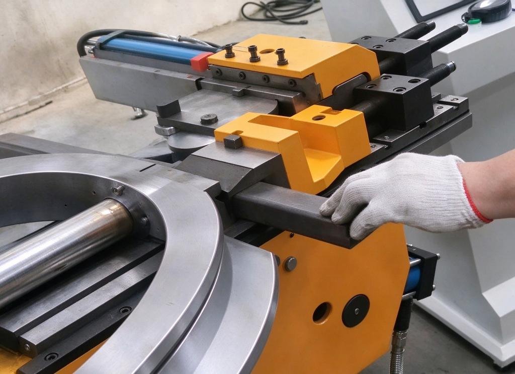
Air-conditioner Tube Bending Machine: Turning Soft Thin-Wall Copper into Leak-Tight Hairpin Coils at Production Speed
News 2026-11-19
On the production line of a modern air-conditioner factory, condenser and evaporator assemblies move forward in increments measured in seconds. Fins are stacked, tube-expansion stations stand ready, and between these two processes sits the step that decides whether thousands of copper tubes can become qualified heat exchangers: tube bending. The air-conditioner tube bending machine is the core equipment of this step. Within fractions of a second, it must form a soft annealed copper tube with a wall thinner than one millimeter into a U-bend or hairpin bend that is dimensionally accurate, smooth on the inside, and entirely free of wrinkles.
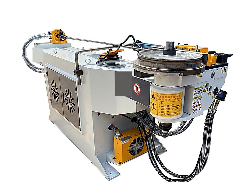
The task looks simple. In reality it concentrates some of the most demanding requirements anywhere in tube forming: the softest material, the thinnest walls, the lowest tolerance for defects, and the fastest production takt in the industry.
Recent industry observation shows that as inverter multi-split systems, heat pumps, and new refrigerant platforms spread across global markets, downstream manufacturers are placing unprecedented demands on the precision and stability of bending equipment built for air-conditioning tube work. This report examines the technical logic that separates a purpose-built air-conditioner tube bending machine from a general-purpose bender.
Why Air-Conditioning Tubing Is the Most Unforgiving Application in Tube Bending
Copper tube used in air-conditioning and refrigeration systems is, among common bending materials, both the easiest to form and the hardest to control. Annealed copper has high elongation and bends readily; but that very softness makes it acutely sensitive to support. A thin-wall copper tube without adequate internal support flattens the moment it bends, and wrinkles appear with the slightest imbalance in tooling.
Across the industry, refrigerant tubing wall thickness generally falls between 0.75 mm and 1.1 mm. For R410A systems, a 9.52 mm copper tube typically carries a wall of about 0.8 mm; a 19.05 mm tube supplied in coil form requires roughly 1.1 mm to withstand handling and operating pressure. Behind these numbers lies the high-pressure safety boundary of the refrigerant circuit — and a very small material margin for bending deformation. If wall thinning on the outside of the bend exceeds its allowance, the bend becomes the weakest point in the entire tube circuit.
Put simply: a structural tube bender aims to “bend it, and bend it to shape.” An air-conditioner tube bending machine aims to “bend it so the tube still withstands twenty years of refrigerant pressure cycling afterward.”
How Many Bends Hide Inside One Air Conditioner
Consumers rarely realize how much bent tube sits inside a split system or a commercial VRF unit. Inside the heat exchanger, straight tubes passing through the fin pack must be formed into 180-degree long-U bends that connect the tubes of one row into a continuous circuit; the long-U tubes are then joined by short-U bends with pre-fitted brazing rings. Around the compressor, the four-way valve, and the high- and low-pressure service valves of the outdoor unit, compact copper elbows route the circuit through tight spaces. The installation lines connecting indoor and outdoor units are bent on site as well.
These bends fall into three families. First, the mass-produced 180-degree hairpin bends inside heat exchangers — enormous in quantity, where dimensional consistency is everything. Second, small-radius transition bends inside the chassis, where space is tight and radii often approach 2D or less. Third, field-installed connector bends, which are single-piece and made on site. Air-conditioner tube bending machines serve mainly the first two families — precisely the ones with the highest quality and takt requirements.
The 180-Degree Hairpin Bend: The Skeleton Step of Heat Exchanger Production
In heat-exchanger manufacturing terminology, forming straight tube into long-U shapes is called the “long-U bend” or “hairpin bend,” and the machines that perform it — hairpin tube benders — are signature equipment on any evaporator and condenser line.
The difficulty of the hairpin bend lies not in bending itself but in consistency. The leg spacing of each U-bend, the parallelism of the two legs, and the flatness of the open ends directly determine whether the tube can be inserted into the fin holes and pass through the subsequent expansion process. If a tube carries even a barely visible tilt, the expansion tool works off-axis, scratching tube ends at best and splitting them at worst. Industry experience indicates that a hairpin bender needs angle control within ±1 degree and repeatability at the 0.05 mm level to connect reliably with automated tube expansion.
The bend section is also part of the refrigerant flow path. Ripple and ovality on the inside of the bend raise local flow resistance, induce additional turbulence, and over long service lives can become initiation points for vibration fatigue. That is why high-end heat-exchanger process documents carry separate acceptance clauses for the inner-wall condition of the U-bend section.
The Three Classic Defects of Thin-Wall Tube: Wrinkling, Flattening, and Thinning
The three classic defects of thin-wall tube bending show up with particular clarity in copper.
The first is wrinkling. During bending, metal on the inside of the arc is compressed; without support, the wall folds like an accordion into wavy corrugations. Wrinkles raise flow resistance, and their valleys concentrate stress — natural starting points for fatigue cracks. The three high-frequency causes of wrinkling are well established: insufficient pressure-mold (anti-wrinkle) force, a mandrel positioned too far back to support the tube, and a bending radius smaller than the forming limit of the material. The countermeasures are equally clear — increase clamping force, feed the mandrel forward, enlarge the radius, or upgrade the support system.
The second is flattening. Tube cross-sections naturally tend toward ovality during bending, and soft thin-wall copper exaggerates the tendency. Engineers quantify it as ovality — the difference between the major and minor axes of the deformed section as a percentage of original diameter. Excessive ovality reduces pressure-bearing capacity and disrupts tube-end insertion and brazing alignment.
The third is wall thinning. Metal on the outside of the arc stretches and thins while the inside thickens; this is the fundamental physics of bending. Cold-bending studies of U-bent heat-exchanger tube show that beyond ovality and thinning, the process also leaves residual stress and pre-damage in the bend. When deformation exceeds roughly 10 percent, applicable standards call for a formal forming-process qualification to verify that the bending parameters are correct. The same logic applies to copper tube in heat-exchanger work.
Mandrel and Nose Advance: The Invisible Hand Behind Bend Quality
For thin-wall copper, the mandrel is nearly the decisive component. It provides an active internal support surface that holds the tube close to its original cross-section at the instant of bending. Field troubleshooting of wrinkled hairpin bends follows a consistent sequence: first check whether the mandrel diameter matches the tube’s inner diameter, then whether the mandrel position is correct, and only then examine the wall thickness and temper of the copper itself.
Setting mandrel position is the practice known as nose advance control. The rule of thumb is to push the mandrel nose slightly forward of the tangent point of the bend die. Too far forward, the mandrel scratches the inner wall and increases retraction drag; too far back, support fails and wrinkling and flattening appear immediately. For extreme 1D-radius bends, a ball-type mandrel with articulated segments is mandatory — its flexible balls follow the bending trajectory and support the inside of the arc segment by segment, something a rigid straight mandrel cannot do.
One easily overlooked detail in air-conditioner copper work is lubrication between mandrel and tube bore. Soft thin-wall copper tolerates dry friction poorly: it scores the inner wall, and the retraction stroke can re-deform the bend that was just formed. Mature lines manage lubricant quantity and application position as formal parameters — managed with the same discipline as bend angle.
Anti-Wrinkle Mold and Pressure Mold: Stopping Ripples Before They Start
Where the mandrel supports from inside, the anti-wrinkle mold steadies the tube from outside. Mounted just before the tangent point, its working surface extends along the bending direction, holding the compression-side wall so waves cannot form at the moment bending begins. Pressure-mold force is the second field variable: too little force invites wrinkles, too much mars the tube surface, raises drag, and leaves visible clamp marks on soft copper.
For this reason, the die adaptability of an air-conditioner tube bending machine has become a key selection criterion. One machine must cover a family of diameters — 7, 9.52, 12.7, 15.88, 19.05 mm and beyond. Changeover precision of the die set and parameterized storage of clamping forces determine whether the line returns to full quality within minutes. Equipment that stores these values with the part program is the only kind that deserves the name “CNC.”
Springback Compensation: Copper’s Elastic Memory
Annealed copper is soft, but its springback is not negligible. After unloading, the tube “remembers” its elastic state and opens back by an angle, while the radius relaxes slightly outward. For 90-degree bends, compensation is an empirical over-bend correction. For 180-degree hairpin bends, springback shows up in leg spacing and opening width: insufficient compensation splays the legs so they will not enter the fin pack, excessive compensation narrows them so the assembly will not fit either.
The common practice on CNC air-conditioner benders is a springback compensation table by material batch: the program adds a compensation value to the target angle, the first article is verified, and the value is locked. Mechanical properties between copper batches vary only modestly, but differences in annealing state are enough to shift compensation — hence the industry norm of “calibrate by batch, confirm on first article.” The ±1-degree accuracy figure is achieved inside exactly this closed loop.
Bending Radius: Pushing Toward the 2D Boundary
Compact chassis design keeps pushing bending radii downward. For general structural tube, the economical range sits between 2D and 3.5D, while small-radius transition bends in indoor units already approach 2D or less. The working rule is well known: once the radius drops below 3D, the risk of inside wrinkling and section distortion rises sharply, and mandrel type and anti-wrinkle conditions must be upgraded accordingly.
For heat-exchanger long-U bends, radius also touches flow performance. Too small a radius raises resistance in the bend section and disturbs the hydraulic uniformity of the exchanger. Mature U-bend processes therefore do not chase minimum radii; they balance flow resistance, formability, and tube-insertion assembly. This is why hairpin bender die sets concentrate in the 2D-to-3D range.
From Hydraulic to Servo: Takt Time and Single-Setup Forming
Early air-conditioner copper bending relied on hydraulic semi-automatic machines — one bend, one motion, quality riding on the operator’s hands. The current trend is comprehensive servo-CNC conversion: feed, rotation, and bend axes all closed-loop, combined with automated loading and coordinated mandrel timing, so a long-U bend completes in a single setup at second-level takt.
Servo conversion delivers more than speed. CNC benders with 0.05 mm repeatability are now common in the industry, which means thousands of U-bends produced on one program show negligible drift in angle and leg spacing. For heat-exchanger tube bundles of dozens of tubes — where every bundle must be interchangeable with the next — this capability directly determines the automation rate of the expansion process. Poor bundle consistency forces automated expansion machines to stop and wait for manual intervention.
A further trend is process integration: bending, end cutting, chamfering, and brazing-ring fitting consolidated into one station on short-U lines, while the long-U-then-short-U assembly sequence is already fully automated. The smoother the interfaces between machines, the lower the operator-per-machine ratio on the exchanger floor.
Quality Verification: From Cross-Section to Leak Test
Air-conditioner bend acceptance follows a clear inspection chain. Geometrically, angle, leg spacing, and leg parallelism are measured. Cross-sectionally, cut samples are checked for ovality and wall-thinning rate, with metallographic inspection where needed to confirm the inner wall is wrinkle-free and undamaged by the mandrel. At system level, bends must pass leak and pressure tests as part of the finished circuit — and high-pressure refrigerant systems such as R410A show no mercy to the weakest point.
The formal expression of this discipline is the forming-process qualification: whenever deformation or thinning exceeds agreed thresholds, or new material and new tooling are introduced, bending parameters must be validated by producing sample bends, sectioning and measuring them, and where required running fatigue and burst verification. The logic descends from the pressure-piping world, compressed here into air-conditioning production takt.
Selection Criteria and the Road Ahead
Synthesizing recent industry practice, selecting an air-conditioner tube bending machine comes down to five essentials. First, diameter coverage and changeover efficiency — can the machine switch rapidly across the 7 to 22 mm family? Second, angle accuracy and springback compensation, with ±1 degree as the hard criterion. Third, mandrel system configuration — support for ball-type mandrels and parameterized nose-advance control. Fourth, axis count and takt capability — servo control on at least three axes with automatic loading and unloading. Fifth, connectivity with downstream expansion, brazing, and leak-testing processes, including standardized tube-bundle trays.
Looking forward, two principal themes stand out. One is refrigerant-driven redesign of wall thickness and pressure ratings, where both thinner and heavier walls require recalibrated process windows. The other is data: linking every tube’s bending parameters and first-article measurements into factory systems so bend quality evolves from hand-feel experience into traceable digital assets. Against a backdrop of sustained heat-pump and multi-split market growth, the air-conditioner tube bending machine is evolving from “a machine that can bend” into “a process system that guarantees consistency.” That evolution is now the competitive focus of equipment builders — and the hidden dividing line in yield competition for every manufacturer downstream.