Tubes & Tube Bending Machines: The Six Variables That Decide Whether a Bent Tube Fits the First Time
News 2026-11-10
Why a Bent Tube Deserves More Attention Than It Gets
In most metal structures the bent tube is not the star. Frames, seat skeletons, guardrails, fluid lines, the support arms on gym equipment — the curved tube is the connector that holds everything else together. But it is precisely this connector that is best at amplifying every upstream tolerance someone chose to live with, and then releasing all of that accumulated error at the assembly station.
The cost of a bent tube has never been just material plus machine time. The real cost sits in the hours burned on first-article trials, in the downtime spent reworking tooling, in the small percentage of parts in every batch that need hand straightening or end up in the scrap bin, and in the week of production scheduling that slips because one new tube geometry refuses to come into tolerance. What makes tube work difficult is not producing a bend. It is producing the five-thousandth bend in the same tolerance band as the first.
That is why tubes and tube bending machines have to be discussed together. The incoming condition of the tube sets the physical ceiling of what can be formed; the axis count, structural stiffness and control resolution of the machine determine whether that ceiling can be reached repeatably; and the process parameters are the translator between the two. Optimize any one of them alone and the other two will quietly cancel the gain.
Variable One: Wall Thickness Tolerance and Heat-to-Heat Yield Strength
The input to a bending operation is almost never as standard as the drawing suggests. Two coils of tube with the same grade, the same outside diameter and the same nominal wall can differ by several percent in actual wall thickness and by more than ten megapascals in yield strength. On a straight section this is irrelevant. On a bend, it becomes drift in springback.
A batch on the thin side of tolerance reaches the critical wall-thinning limit sooner and gives the inner wall a narrower window before it wrinkles. A batch with higher yield strength springs back further, so running the previous batch’s program produces angles that are consistently a degree or so shallow. The result is a familiar pattern: the first article passes, the second passes, a new coil goes on the mandrel and the whole run shifts — and the operator concludes the machine has drifted.
The disciplined approach moves material data upstream into process design. Log the heat number and measured wall at goods-in, run one trial bend per batch to confirm the springback angle, and write the correction into the program instead of leaving it to the operator’s hand. Seamed tube carries an additional rule: the weld must be kept out of the tension and compression zones of the bend, or the crack will start at the seam. It sounds obvious, yet it is routinely broken in practice because the tube on the rack happens to be sitting weld-up.
Variable Two: The Ratio of Bend Radius to Wall
Bend radius is not a free choice. The tighter the radius, the greater the tensile strain on the outer fibers and the more severe the thinning; the greater the compressive strain on the inside and the stronger the tendency to wrinkle. Engineering practice usually holds to an empirical boundary: a bend radius of at least three and a half times the outside diameter for ordinary tube, and at least five times the outside diameter for high-pressure or pressure-retaining lines. This is not dogma. It is a rough discount rate that keeps strain inside what the material can survive.
When a design genuinely needs a tight radius for packaging reasons, the process has to change its vocabulary: a mandrel that follows the inner wall more closely, a tighter clearance between mandrel and bore, stronger anti-wrinkle support, and where necessary a switch to hot bending or packed bending. The price is a slower cycle, more expensive tooling, and far greater sensitivity to incoming material consistency. A mature design review therefore asks whether a radius can be produced economically while the drawing is still open, rather than leaving process engineering to rescue it during trial production.
Variable Three: Four Failure Modes and Where They Come From
Four things happen at once during a bend, and each one maps to a failure mode.
Wall thinning on the outside comes from tensile strain. Once the thinning ratio passes what the material allows, the surface necks and then tears. It is governed directly by bend radius, friction conditions, and whether boost or push assistance is actually working.
Wrinkling on the inside comes from compressive strain. A thin wall cannot carry the compressive stress at large strain, and waves form along the inner arc. Once formed, a wrinkle is effectively impossible to remove downstream; the part is scrapped or downgraded.
Ovalization comes from insufficient radial constraint. Roundness drops after bending, and if that tube has to accept a fitting, pass over a shaft or hold a seal, ovality becomes the assembly killer.
Springback comes from elastic recovery after unloading. It produces no visible defect, yet it moves angle and radius away from target at the same time, and it is the single largest source of dimensional non-conformance. Springback depends on yield strength, elastic modulus, the relative bend radius and the wall-to-diameter ratio. It cannot be eliminated. It can only be compensated.
The practical value of separating these four is diagnostic speed. When a part fails, the process engineer can tell within minutes whether this is a parameter problem or a tooling problem. Thinning and cracking point to mandrel and lubrication. Wrinkling points to anti-wrinkle support and boost. Ovalization points to mandrel fit and clamping. Springback points to the compensation model. Pick the right direction and setup time collapses from days to hours.
Variable Four: Mandrel Type and Its Three Parameters
The mandrel is the most underrated component in the whole process. It sits inside the tube, supports the inner wall just ahead of the deformation zone, and prevents collapse and wrinkling. Common forms include the cylindrical, the round-nose, the arc, the ball-socket and the round-nose ball-socket types. The difference between them is not sophistication. It is which failure mode each one suppresses.
Solid cylindrical and round-nose mandrels are simple and stiff, and they support thick-wall parts at tight radii very well. On thin-wall tube, though, their contact with the bore is effectively point-like, and the outer-wall thinning rate tends to run high. An arc mandrel presents a spherical profile that follows the inner wall of the deformation zone more continuously, and it visibly reduces thinning. Articulated ball-socket and round-nose ball-socket mandrels string several knuckle segments together so the mandrel can bend with the tube, and they perform best on complex three-dimensional bends and consecutive multi-radius work — at the cost of complexity, higher maintenance demands and much tighter clearance control.
Three parameters matter more than the type itself: mandrel diameter, which sets the clearance to the bore; mandrel extension, which positions the support point relative to the tangent; and the number and spacing of knuckle segments on articulated types, which sets flexibility. Clearance that is too tight scores the bore and adds friction and feed resistance. Clearance that is too loose removes the support and the wrinkle returns. Too little extension leaves the deformation zone unsupported; too much drives the nose into the inner wall. None of these has a universal answer. They are established per material, per diameter-to-thickness ratio and per radius ratio, then frozen into a process card.
Variable Five: Die Set and Clamping Stiffness
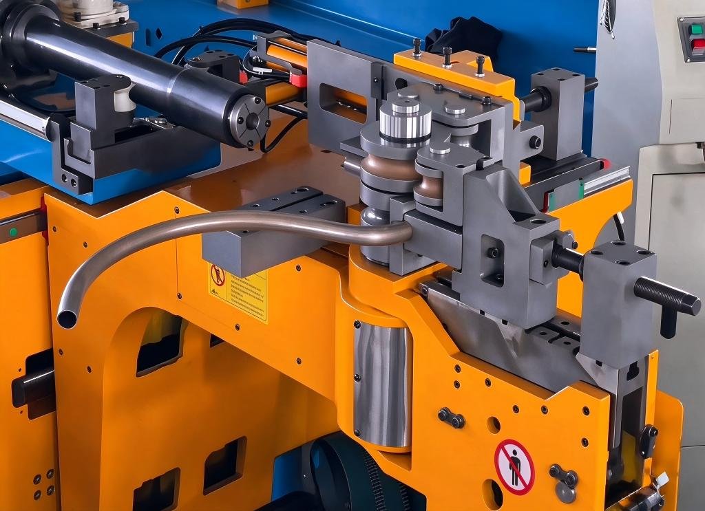
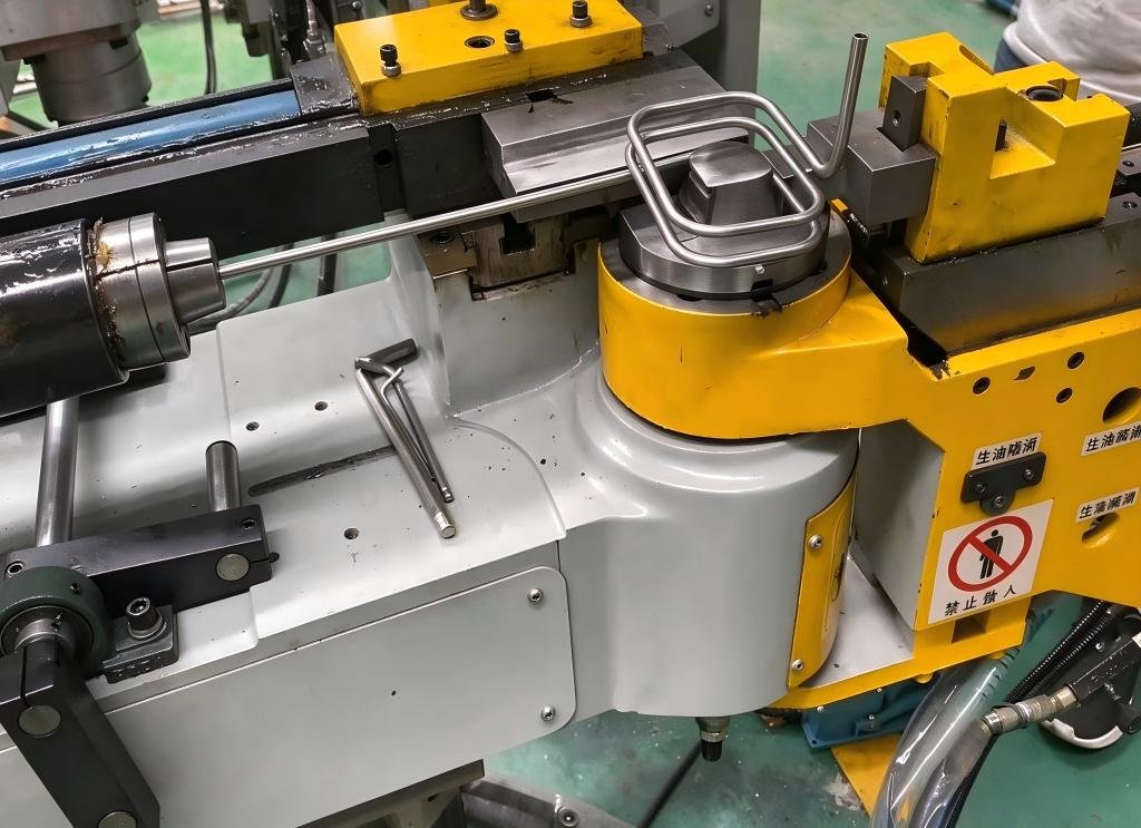
What actually forms the tube is not the spindle. It is the die set. The bend die sets radius and section shape. The clamp die holds the tube end firmly against the bend die. The pressure die provides lateral support and friction control as the tube enters the deformation zone. The wiper die backs up the inner arc on thin-wall parts and suppresses the start of a wrinkle.
If any element in that set lacks stiffness, the symptom presents as dimensional instability. A clamp that does not hold lets the tube slip relative to the bend die, the tangent point drifts, and the developed length of the entire part is wrong. Insufficient pressure die force lets the tube bulge at the tangent. A wiper set half a millimeter off position becomes the origin of the wrinkle. A large share of complaints about “the machine isn’t accurate enough” end with worn tooling or a die that was never seated properly.
The other hard constraint on tooling is cost and changeover. One bend die serves one radius, one clamp serves one outside diameter, and a single product family can need a dozen sets. In high-mix, low-volume work, die count and changeover time decide whether the line is economic at all. That, far more than showmanship, is the real reason multi-stack dies, multi-radius dies and automatic die-change architectures have become common: they compress changeover from hours into minutes.
Variable Six: Springback Compensation, Tangent Correction and Cut Length
If bending is a prediction problem, the process engineer has to predict three things: how far the tube will spring back, where the bend will actually start, and how long the blank should be cut.
Springback compensation is usually written into the program as an angle offset. Target ninety degrees, measure eighty-seven and a half, set the programmed angle near ninety-two and a half, then iterate to convergence. But compensation is not permanent. A new material batch, new tooling or a change in lubrication all shift it, so a stable line keeps a closed loop of bend, measure, correct rather than treating one compensation value as eternal truth.
Tangent correction handles a different error: after clamping, the theoretical tangent and the point where deformation actually begins are not the same place. Clamp length, tube end squareness and gripper slip all contribute. Left uncorrected, every bend on the part translates as a group, and holes no longer line up at assembly.
Cut length is the most easily overlooked item of the three. Bending changes developed length slightly but cumulatively, and on a part with three or five bends the thinning and extension of each bend stack up. Accurate cut length is not mainly about saving material. It is about keeping the end allowance inside a controllable window after the last bend.
Machine Level: Axis Count Is Not Accuracy
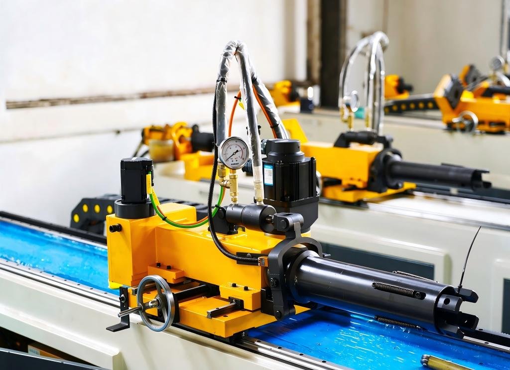
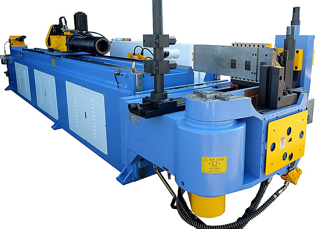
Discussions about tube bending machines drift easily into an axis race — three, five, eight, ten — as though more axes were inherently better. Axis count defines what a machine can do. It does not define how stably it does it.
What governs stability is whether the axes are genuinely synchronized, whether the bed and bend arm have the stiffness to resist bending reaction, whether the feed gripper repeats its position, and whether the control can translate three-dimensional tube data into a collision-free motion sequence. A servo-driven, all-electric machine will still lose every bit of its control resolution to elastic twist if the bed deflects under full bending load. Conversely, a structurally solid machine with well-matched tooling can hold extraordinary repeatability on a fixed family of parts even with modest axis count.
The same caution applies to the word automatic. Automatic means feed, rotation, bend and unload are sequenced by program with minimal operator intervention. It does not mean the process is correct. If the program carries the wrong compensation value or the wrong mandrel extension, the machine will simply produce scrap faster and more consistently.
Inspection and Consistency: Allocating Error Properly
The tolerance on a bent tube is not a single number. It is an allocation. End-to-first-bend distance, straight length between bends, angle at each bend, the spatial rotation of each bend plane and the final position of each tube end each carry their own band. In assembly failures it is rarely one dimension out of tolerance; more often several dimensions are sitting at their limits and the accumulation lands on the tube end.
Inspection therefore focuses on first-article and audit measurement of the end-point coordinates in space — three-dimensional measurement or a dedicated check fixture that confirms the whole tube’s spatial attitude — rather than caliper readings section by section. Once the first article is approved, the line moves into monitoring, and capability replaces final inspection. When the distribution of one dimension begins to drift to one side, a variable is moving: tooling wear, a material batch change, or a compensation value that is due for update.
The Direction of Travel: From Bendable to Predictable
Tube forming is now walking the same road machining walked before it: away from the feel of an experienced hand, toward models and data.
Simulation comes first. Finite element analysis now predicts wall thinning and wrinkle tendency across mandrel types reliably enough to move trial and error off the shop floor and onto a screen. Engineers screen out the obviously unworkable options in the model and validate only the one or two survivors on the machine.
In-line compensation follows. Measuring the actual angle and position after the bend and writing the correction back into the program reduces dependence on manual trial bends. The value is largest in high-mix, low-volume work with frequent changeovers.
Unmanned cells come next. Bending is absorbed into an automated unit that takes cut and deburred tube in front and hands it to end forming, punching and welding behind, joined by robots and conveyors. The bottleneck in such lines is rarely the bending itself. It is the repeatability of how the part is located between operations — which returns once again to the theme of consistency.
Modular, quick-change tooling is the fourth thread. If high variety is the normal condition, compressing changeover beats shaving another second off cycle time almost every time.
Conclusion
The relationship between tubes and tube bending machines is fundamentally a matching problem between what the material can do and what the equipment can hold. Whether a bent tube fits on the first attempt depends on whether incoming material was taken seriously, whether radius and wall were paired sensibly, whether the mandrel and die set were chosen against specific failure modes, whether compensation and cut length form a closed loop, and whether the machine is stiff enough to make its control resolution real.
None of these variables is complicated on its own. What is difficult is that they are coupled. Change the radius and the mandrel changes, the compensation is recalculated, the tooling is remade. Change the material batch and everything established in trial may become invalid. High-quality tube production has never been bought with a more expensive machine. It is built from a process system that pins these variables down, so that getting it right the first time is no longer luck but a repeatable result.