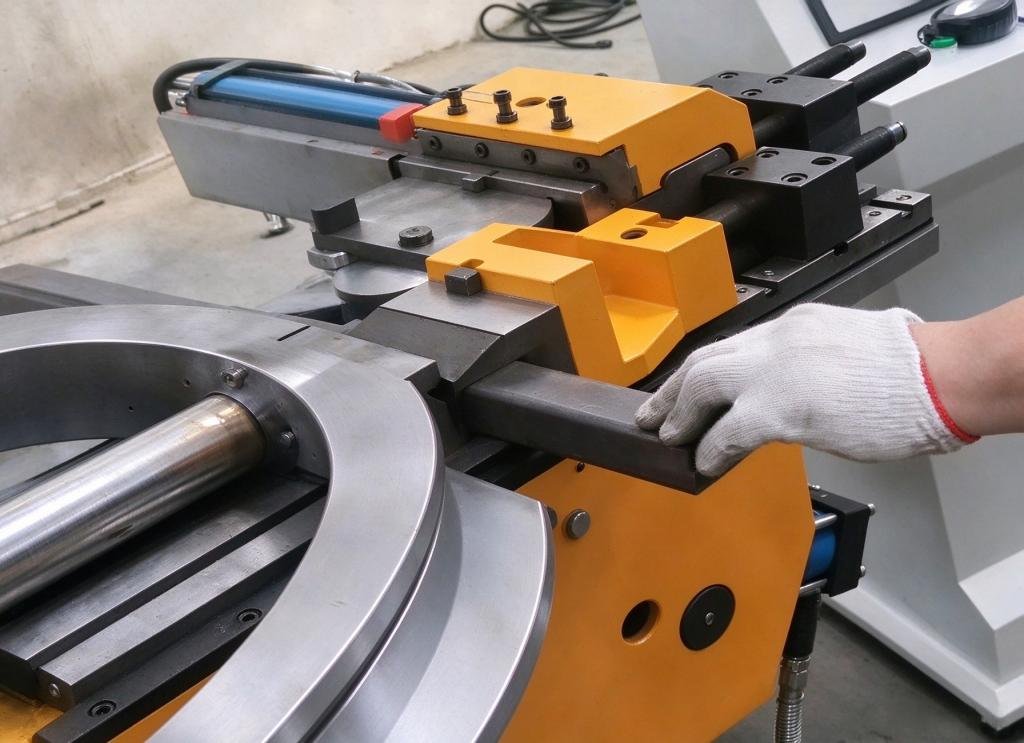
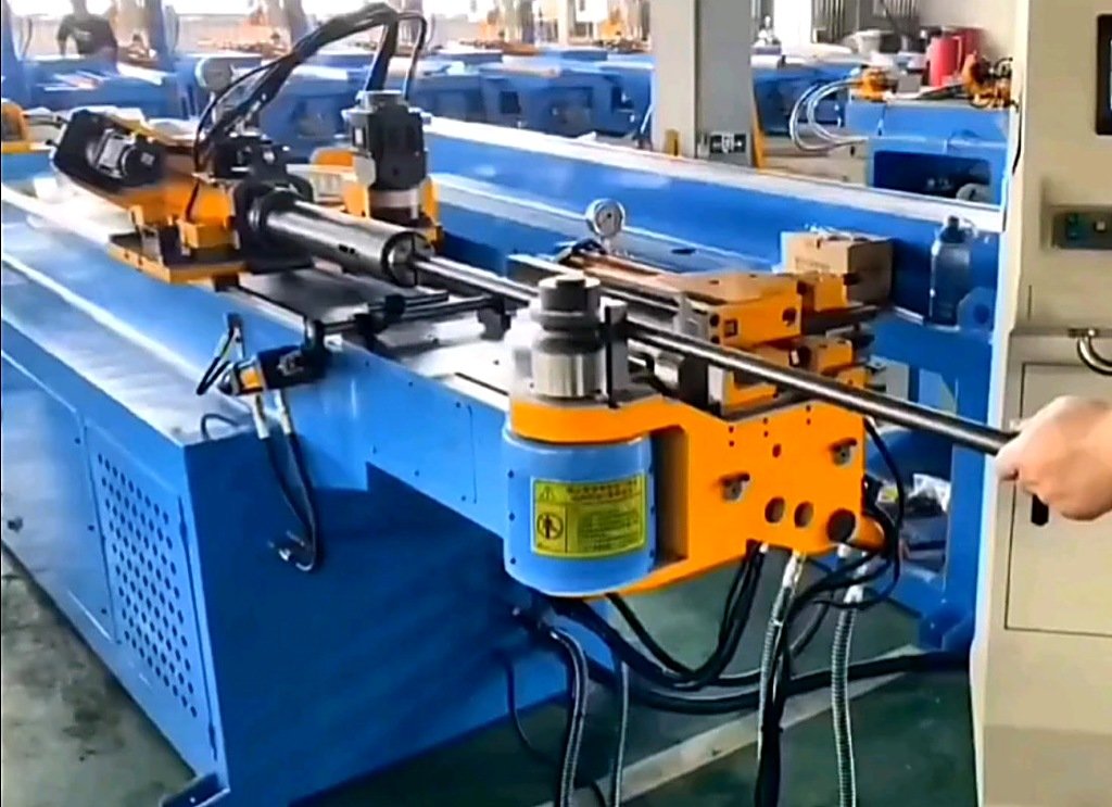
Aircraft Seat Tube Bending Machine: How a Single Bend Sets Seat Frame Weight, Crash Load and Assembly Fit
News 2026-11-18
Passengers see a cushion and a cover. Engineers see a load path made of a few dozen thin-wall tubes, sheet metal brackets and fittings. An aircraft seat is one of the very few assemblies in a cabin that has to satisfy three contradictory demands at once. It has to be light, because every kilogram carried in a cabin is fuel burned for the life of the airframe. It has to be strong, because under the inertia loads defined for an emergency landing it must stay intact and must not let the backrest or the seat pan intrude into the occupant’s survival space. And it has to fit, because after tolerances have stacked up across a dozen parts it still has to drop into the seat track fittings without a fight.
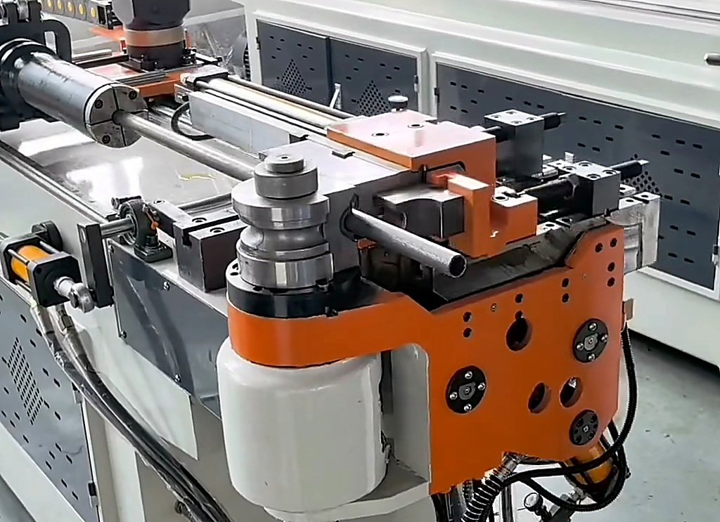
Those three demands are usually owned by three different groups — structures, certification and manufacturing engineering. They meet, physically, at one operation: tube bending.
Why a Seat Frame Is Almost Always a Bent Structure
Strip a seat down to its skeleton and a simple rule appears. Anywhere a corner can be formed, it is formed — not welded.
The seat pan frame is typically a ladder: several vertical tubes crossing several horizontal tubes, with the rim turned into a curved flange. The backrest is an open U or portal frame, its top rail raked slightly toward the occupant, its lower ends pivoted to the pan. Armrests, struts and footrest supports are single- or double-bend small tubes. Small section, thin wall, long length, many bends per part.
The reason for bending rather than fabricating corners is straightforward. A well-formed bend replaces two parts, four weld beads, a post-weld straightening operation and a weld inspection cycle. Welds are where fatigue cracks prefer to begin, and under repeated pressurization cycles, take-off and landing vibration and passenger leaning loads, one inconsistent weld can cut the life of the whole frame. A bend, by contrast, keeps the load path in continuous fibre flow. Material is redistributed along the bend direction, and stress does not have to cross a fusion line. For a weight-critical structure this is worth a great deal: the natural thickening on the outside of the bend sits exactly where bending moment peaks.
The price is that bending concentrates every precision requirement into one operation. Whether a frame assembles and whether it passes its tests is largely decided while the tube is still clamped in the machine.
Three Objectives Pulling Against Each Other
The first instinct in lightweighting is always to reduce wall thickness. Take an aluminium tube from 1.5 mm down to 1.2 mm and the part loses roughly a fifth of its mass; across a full frame that adds up. But as the wall thins, the thinning percentage on the outside of the bend becomes sensitive. A smaller starting wall means the same absolute loss is a larger fraction, and the allowable is normally written as a fraction. The result is the classic three-way pull: design wants thin, process wants thick, and certification only looks at the result.
The second pull comes from load. Transport category airworthiness requirements for seats call for the seat to remain intact under defined emergency landing inertia loads and to pass sled impact tests at 16 g forward and 14 g downward, with velocity changes of about 13.4 m/s and 10.7 m/s respectively. Under a pulse like that the frame is not simply in bending; global instability and local buckling are coupled. A wrinkle, a flattened section or an over-thinned wall at a bend is effectively a pre-installed buckle initiator. Seat frame bending therefore lives in a different category from general structural bending: the tube has to come out clean, not merely formed.
The third pull is assembly. A seat is not a standalone part. It lands on seat track fittings through joints, the backrest pivots to the pan, armrests line up with side panels. The end point of a three-dimensional bent tube is the superposition of four error sources — feed length, bend angle, spatial rotation and springback compensation. A single tube may be out by a few tenths of a millimetre, but a dozen tubes assembled together will accumulate in the same direction. The complaint heard on the floor is rarely “the tube is wrong”. It is “every part passes, and the assembly still misses”.
Springback Is Not One Number but a Drift in Three Directions
The most underrated effect in tube bending is the compounding of springback.
During bending the outer wall is in tension and the inner wall in compression. On unloading, the elastic portion recovers: the bend angle opens, the bend radius grows, and the tube axis shifts. These three changes are not independent. Angle recovery turns the end point, radius growth changes arc length, and the two together lift or drop the tube in space. On a single-plane, single-bend part this drift can be absorbed by one angle offset. On a multi-bend three-dimensional part, the drift restarts at every bend, the error is carried forward segment by segment, and it shows up at the last flange or fitting hole.
Aluminium is particularly awkward here. Its elastic modulus is roughly a third that of steel, so at the same radius-to-thickness ratio the springback angle is several times larger. Common practice is to build a compensation table: bins by alloy, temper, diameter-to-wall ratio and relative bend radius, each assigned an over-bend angle and a radius correction factor. A table handles the systematic part. It cannot handle the scatter. Within one alloy, yield strength can vary by tens of megapascals between heats, and wall thickness itself has a tolerance band; the two stack, and springback wanders around the compensated value. This is why some lines produce a beautiful first article and start generating assembly interference around part two hundred.
The stable approach is to treat springback as a controlled variable rather than a rule of thumb. Sample incoming tube mechanically by heat and feed the measured values back into the compensation parameters. Keep the angle and pressure curve of every bend on the machine. Check first, middle and last articles against the same gauge. Springback will not disappear, but it can be confined to a narrow band.
Wrinkling, Thinning and Ovality Are One Window
New operators treat wrinkling, thinning and ovality as three separate defects and hunt three separate fixes, which usually means pushing one problem down and raising another. In reality they are three expressions of one condition: whether the material was guided while it flowed.
The inner wall is in compression and the material has to crowd toward the centre of curvature; where it cannot, it buckles into waves — wrinkling. The outer wall is in tension and elongates, so the wall thins, and past a limit it fractures. The section tends to flatten under the bending moment, which is ovality. All three share the same process variables: mandrel type and position, wiper die fit, clamp pressure, lubrication, bending speed, and above all the relative bend radius.
The tighter the relative radius, the sharper all three become. As a rule of thumb, cold bending aluminium tube without a mandrel struggles below about 2.5 times the outside diameter. With a mandrel and a wiper die the radius can be pushed tighter, but every increment narrows the process window. Seat frame designs tend to land between 1.5D and 2.5D, because a larger radius makes the frame softer, heavier and bulkier — which is precisely the most sensitive part of the window.
Mandrel Choice: Integral Versus Articulated
The mandrel is the part of tube bending that still feels like craft, and also the part most amenable to standardisation.
Five types dominate: cylindrical, round-head, arc, ball-socket and round-head ball-socket. The first three are integral; the last two are articulated, built from a chain of spherical or socketed segments. Integral mandrels give rigid support, suppress section flattening effectively and are good at controlling outer-wall thinning. Articulated mandrels follow the tube around the bend and suit small radii and large bend angles, but because there are gaps between segments the internal support is intermittent and the thinning rate on the outer wall rises.
Comparative work on thin-wall tube is instructive. Under articulated mandrels — ball-socket and round-head ball-socket — the outer wall thinning rate is higher than under integral types such as cylindrical, round-head and arc. The arc mandrel performs best at reducing outer-wall thinning. The ball-socket mandrel gives the best overall forming quality, balancing wrinkling, ovality and thinning. The ranking makes the point: there is no best mandrel, only the right mandrel for a given part.
Selection really rests on three inputs: diameter-to-wall ratio, relative bend radius, and the elongation of the material in the bend direction. Large diameter-to-wall ratio with a tight radius pushes toward articulated; thicker wall with a generous radius favours integral, which is also simpler and more durable. The hard part is not choosing but changing. A line running several frame tubes needs fast mandrel changes, and after each change the mandrel advance reference has to be reproducible. If the reference is not reproducible, every earlier decision about mandrel type is wasted.
Mandrel Advance and Wiper Die: Where Setup Is Really Won
If a bending shop could keep only one setup parameter, most experienced operators would keep mandrel advance — how far the mandrel nose leads the tangent point of the bend.
Too little advance and the mandrel has not reached the deformation zone before the inner material starts to pile up; regular waves appear on the inner wall. Too much and the nose pushes too far forward, friction rises, the outer wall is dragged thinner, and in bad cases the nose scores the bore. The sweet spot is often one or two millimetres wide, and it moves with tube heat, lubrication and die wear.
When chasing wrinkles on the floor, three causes deserve checking first. Is the main clamp slipping? Insufficient clamping force lets the tube be drawn forward during bending, and the feed length is then meaningless. Is the clearance between mandrel and bore too large? With a loose fit the mandrel cannot support the wall and might as well not be there. Is there a gap between the guide clamp and the bend die? That gap lets the tube creep tangentially, and the wrinkle starts there. Rule these out before touching advance or the wiper.
The wiper die provides back pressure to the inner wall so the material has nowhere to bulge. Its contact face has to align exactly with the bend die tangent; once worn, a step appears and wrinkles track the step. Many lines run a wiper until it can no longer be used, which in practice means paying for die life with product tolerance.
Multi-Radius and Three-Dimensional Bends: The Value of One Setup
Seat frame tubes rarely carry a single radius. A backrest frame often has one large radius across the top rail, a smaller radius on each side and a transition between them; a pan flange may have continuously varying curvature. Divided across several setups, every re-clamp introduces a new datum error, and every re-clamp grips an already-formed shape again — clamping force alone can distort a finished arc slightly.
Forming all bends in one setup is valuable not because it saves time but because it keeps one datum. Every bend is generated on the same tube in the same coordinate system, error accumulates in one direction only, and it can be absorbed by an end-point compensation. This is also why the feed and rotation axes of a three-dimensional CNC bender deserve more attention than its bending tonnage. Tonnage decides whether the tube can be bent; feed and rotation resolution decide whether the result resembles the model.
There is a further detail that is easy to miss on multi-bend parts: springback stacking. After the first bend recovers, the tube’s attitude has already changed, so the starting attitude of the second bend is really the nominal attitude plus the first bend’s deviation. A controller that simply runs theoretical coordinates will accumulate the deviation all the way down the tube. Mature controllers correct attitude after each bend, folding the measured or predicted recovery into the next segment’s starting point. That is the genuinely difficult part of three-dimensional bending.
Weld Seam and Temper: Two Hidden Lines
For welded tube there is an iron rule: keep the seam near the neutral axis, away from the tension side and the compression side. On the tension side the weld reinforcement becomes a stress raiser and cracks first; on the compression side the seam and parent metal deform incompatibly and wrinkle. The seam position on the tube is fixed, so either the tube is rotated during feed to bring the seam to the neutral axis, or the bend direction is fixed at the design stage to suit it.
Temper is the second hidden line. Aluminium tube is commonly formed in the naturally aged condition after solution treatment and then artificially aged to the higher strength temper afterwards. The reason is that the lower-strength condition has better ductility and more manageable springback, so forming rarely cracks; ageing afterwards restores strength and the dimensions stay essentially stable. The reverse route — bending a fully aged tube cold — raises cracking risk sharply, and the only levers are a larger radius or elevated forming temperature. The seemingly easiest route, anneal first and solution treat after forming, is undone by the quench: rapid cooling distorts thin-wall parts appreciably, and the straightening workload usually exceeds the forming difficulty it saved.
From First Article to Series Production: The Definition of Conforming Changes
A good first article depends on an operator’s feel and a machine having a good day. Series production depends on something else: repeat positioning accuracy, die wear management, incoming material consistency, and the ability to freeze setup results into parameters.
Incoming consistency is the most underrated of these. Within one alloy, wall thickness can carry a band roughly ten per cent wide, yield strength varies across a range, and surface condition and residual stress are not identical either. None of this shows up in a single trial part; in production it shows up as runs of heats that bend beautifully followed by runs that never spring back enough. The fix is not to keep adjusting the machine but to treat the key incoming parameters as process inputs and let the compensation follow the material.
Die wear is a second, slower slope. As the bend die groove wears, the tube no longer wraps snugly, and section flattening worsens. As the wiper wears, inner back pressure falls away and wrinkles begin. The change is gradual, and by the time it is visible the product has been running near the tolerance limit for a while. Die life should be managed by part count, not by appearance.
Inspection: Between the Gauge, the Scan and “It Fits”
There are three layers of inspection for bent tube. The first is a check fixture built to the theoretical model: does the tube seat against the key points? The second is a coordinate measuring machine or blue-light scan: a full point cloud compared for section ovality, wall distribution and spatial axis. The third is assembly: mount the tube on the frame tool and see whether the fitting holes line up.
The three frequently disagree. A part that passes the fixture but will not assemble usually means the fixture only checks a few points and says nothing about twist. A part that passes scanning but will not assemble usually means the scan looked at one part while the assembly error is cumulative. The effective approach is to make the inspection language match the assembly language: fixture datums should come from the same source as the assembly tool datums, and the scan evaluation should include end-point spatial position, not only section shape.
For multi-bend seat frame tubes there is also a practical intermediate step: reduce the key bend angles and end-point positions to a quick in-process check, sampled every few dozen parts. It costs far less than full dimensional inspection at the end of the line, and it reveals springback drift as a trend rather than a failure.
What to Look For in the Machine
The phrase “aircraft seat tube bending machine” usually triggers two questions first: how many tonnes, and how large a tube. Both matter, but they decide whether the job can be done, not whether it can be done well.
What actually decides the outcome is a shorter list. Servo axis configuration and resolution: feed and rotation resolution determine spatial accuracy on multi-bend parts, and closed-loop control on the bend axis determines angle repeatability. Springback compensation capability: whether compensation can be built, stored and recalled by material, by heat, by bend number, rather than an operator nudging the angle each time. Die change and datum recovery: whether advance and clamp position return to the same reference after a changeover. Data: whether the pressure, angle and torque curve of every bend is retained, since that record is both the traceability evidence and the only route by which setup experience becomes a process parameter.
One more point is often missed: machine rigidity. The forces in thin-wall tube bending are not large, but their fluctuation is sensitive, and slight elastic deflection in the frame or the bend arm translates directly into angle error. Such error never appears in a static accuracy specification. It appears in production as a slow drift away from nominal.
Conclusion
Take an aircraft seat apart down to weight, strength and fit and the bottom layer is the bend geometry of a handful of tubes. The operation looks simple — clamp, feed, rotate, bend — yet it carries the full weight of materials science, plastic forming, mechanism accuracy and quality management at once. Lightweighting wants it thin. Airworthiness wants it stable. Assembly wants it accurate. There is no permanent balance among the three, only a process window that moves with material, tooling and machine condition.
The lines that hold that window are rarely the ones with the most expensive equipment. They are the ones that have turned every drifting variable into something measurable, recordable and compensable. The real content of tube bending is not bending the tube. It is making the thousandth tube behave like the first.